Difference between revisions of "SCR-263"
Jump to navigation
Jump to search
RadioNerds (talk | contribs) |
|||
| Line 15: | Line 15: | ||
==Components== | ==Components== | ||
| − | * [[BC-443]] | + | * [[BC-443]] Rec. |
* [[BC-444]] | * [[BC-444]] | ||
* [[FT-213]] | * [[FT-213]] | ||
| Line 21: | Line 21: | ||
* [[I-65]] | * [[I-65]] | ||
* [[I-75]] | * [[I-75]] | ||
| − | + | * [[DM-30]] | |
==Reference Files== | ==Reference Files== | ||
Latest revision as of 00:15, 11 December 2015
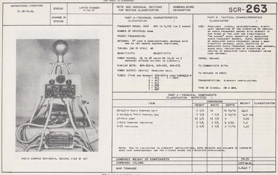
Radio Compass SCR-263-A is intended primarily for use in U. S. Army aircraft and may be remotely controlled from either of two positions. However, installations may be made using only one control position. While the tuning may be accomplished from either of the remote positions, only that position having control may switch bands and functions. The frequency range of the equipment is 200 to 1750 kcs, which is covered in three bands calibrated in kilocycles, as follows:
- band 1- 200 to 410 kcs
- band 2 - 410 to 850 kcs
- band 3- 850 to 1750 kcs.
Only the frequency band in use is visible on the tuning dial. When used in conjunction with the required additional equipment, Radio Compass SCR-263-A is a complete operable equipment capable of providing:
- Visual, unidirectional, right-left indication of the direction of arrival of radio frequency energy with respect to the plane of the loop and simultaneous "On Course" aural reception of modulated radio frequency energy.
- Aural reception of modulated radio frequency energy, using a non-directional antenna.
- Aural reception of modulated radio frequency energy, using a loop antenna.
- Aural-null indications of the direction of arrival of modulated radio frequency energy, using a loop antenna.
Components
Reference Files
![]() Instruction book for radio compass SCR-263-A
Instruction book for radio compass SCR-263-A
- Radio Compass SCR-263-A
- undated
- TO 08-10-64
