Difference between revisions of "R-209~FR"
RadioNerds (talk | contribs) |
RadioNerds (talk | contribs) |
||
| Line 36: | Line 36: | ||
:Radio Receivers | :Radio Receivers | ||
::(Wilcox Electric Types CW3 and F3) | ::(Wilcox Electric Types CW3 and F3) | ||
| − | |||
:Receiver Bay | :Receiver Bay | ||
::(Wilcox Electric Type 113A) | ::(Wilcox Electric Type 113A) | ||
Revision as of 01:12, 24 November 2016
Overview
Radio Receiver R-209/FR is a crystal controlled, super heterodyne AM (Voice), MF and HF receiving equipment designed for use in point to point or ground to air communication and similar applications at fixed plant installations
the equipment consists of a single, panel mounted radio receiver having three panel controls and designed for assembly to a standard relay rack which can accommodate a total of eight such receivers. it may be reset by means of four sets of interchangeable RF coils.
can be mounted with seven other identical receivers, or in any combination of radio receivers R-208/FR and R-209/FR, and installed in a single floor type cabinet to form a single operating bay of equipment.
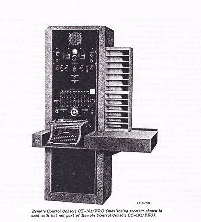
Each receiver so assembled can be individually controlled locally or by means of Remote Control Console CY-161/FRC, from a remote operating point.
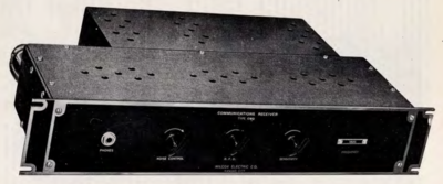
Wilcox CW3
Radio receiver type CW3 is a highly selective crystal-controlled superheterodyne receiver designed for the reception of CW signals. The receiver may be operated at any frequency within the band of 1,950 to 16,500 kHz. The total band is covered by four groups of plug-in coils. The receiver circuit is mounted on a 19-inch panel for rack mounting. It consists of a radio-frequency (RF) amplifier stage, a mixer and high-frequency (HF) oscillator stage, an intermediate-frequency (IF) amplifier stage, a detector and beat-frequency oscillator (BFO) control tube, and an audio-output and output limiter stage. In addition, the receiver contains a rectifier circuit for converting the alternating current (AC) input to the proper direct current (DC) operating voltages. Three controls and a phone jack are mounted on the front panel of the receiver along with a nameplate giving the frequency to which the receiver is tuned. The tubes, coils, and crystal project from the rear of the panel and are covered by a removable dust cover. Connections to the receiver are made through a Jones plug and antenna connector also mounted at the rear of the unit.
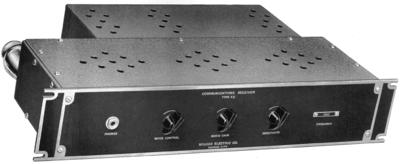
Wilcox F3
Radio receiver type F3 is similar in appearance and functioning to radio receiver type CW3 with the exception that this receiver circuit consists of an RF amplifier stage, a mixer and HF oscillator stage, an IF amplifier stage, detector and automatic-volume-control (AVC) stage, and an output and noise suppressor stage. This receiver also contains its own power supply circuit. Three controls and a phone jack are mounted on the receiver front panel and connections to the unit are made through a Jones plug and antenna connector mounted on the rear panel.
Additional Files
- F3 Radio Receiver
- 1943
- With Addendum April, 3, 1944
- Radio Receivers
- (Wilcox Electric Types CW3 and F3)
- Receiver Bay
- (Wilcox Electric Type 113A)
- November 1945


