Difference between revisions of "AN~PRC-174"
Jump to navigation
Jump to search
RadioNerds (talk | contribs) |
RadioNerds (talk | contribs) (→Images) |
||
| Line 3: | Line 3: | ||
==Images== | ==Images== | ||
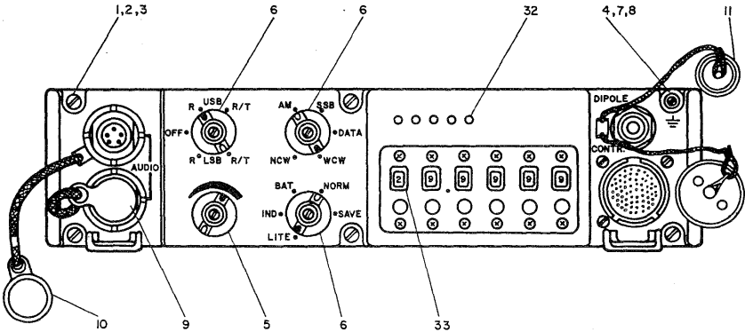
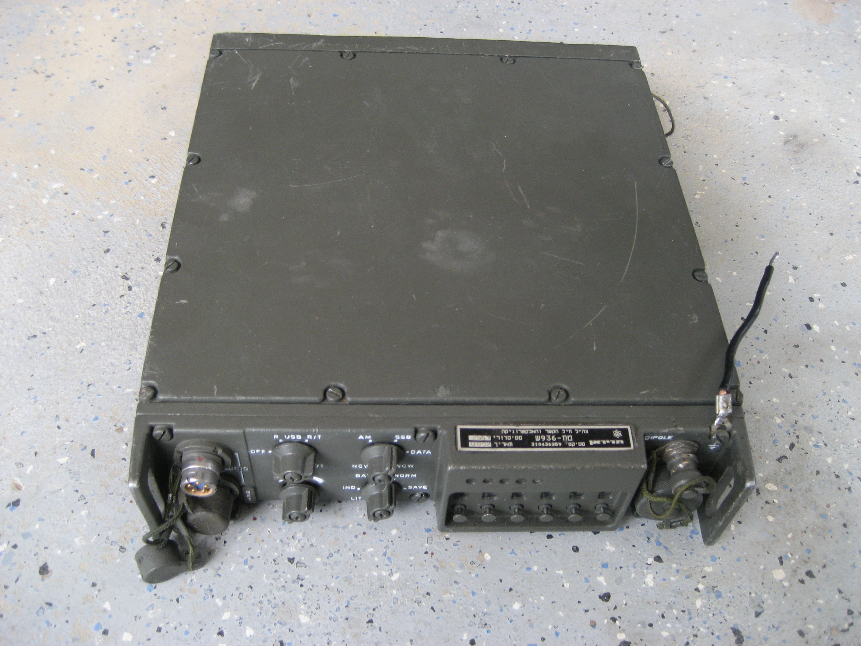
[[File:PRC-174-1.JPG]] | [[File:PRC-174-1.JPG]] | ||
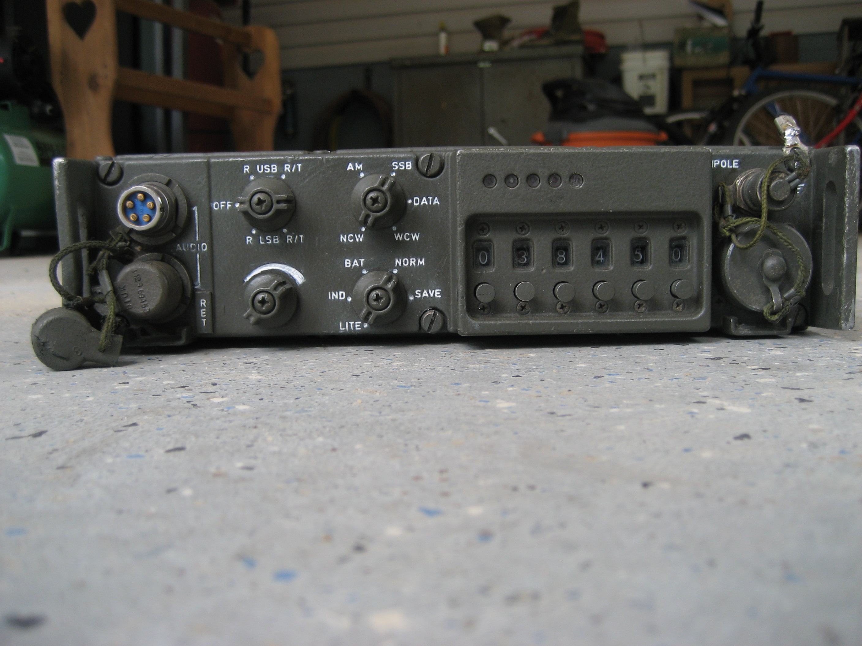
| − | [[File:PRC-174- | + | [[File:PRC-174-2.JPG]] |
==Control Connector Pinouts== | ==Control Connector Pinouts== | ||
Revision as of 13:56, 31 May 2013
Images
Control Connector Pinouts
All BCD levels for frequency control are 12v high to enable that digit.
- 61 Pin Israeli Connector (Small or Hex)
- 1 - X23 1khz BCD8
- 2 - X50 1mhz BCD1
- 3 - X30 10khz BCD1
- 4 - X11 100hz BCD2
- 5 - X10 100hz BCD1
- 6 - X22 1khz BCD4
- 7 - X43 100khz BCD8
- 8 - REM CONT (ground to enable remote control)
- 9 - N/C
- 10 - X51 1mhz BCD2
- 11 - X31 10khz BCD2
- 12 - X12 100khz BCD4
- 13 - IND (high to enable indicator functions)
- 14 - GND
- 15 - VOL REMOTE (remote volume control)
- 16 - BAT IN (battery pack in, might be able to charge with this pin)
- 17 - X21 1khz BCD2
- 18 - X42 100khz BCD4
- 19 - TRANSIT (pulse when 10mhz, 1mhz, 100khz or 10khz are changed)
- 20 - NCW (high when narrow CW is selected)
- 21 - WCW (high when wide CW is selected)
- 22 - DATA (high when data is selected)
- 23 - 12V REM (12 volts when remote is selected)
- 24 - X52 1mhz BCD4
- 25 - X32 10khz BCD4
- 26 - X13 100hz BCD8
- 27 - BATT CHK (high to enable battery check and LED display)
- 28 - TX LEVEL (high to enable power our and LED display)
- 29 - TUNE (high when radio is tuning)
- 30 - FO UNLOCK (high when synthesizer is unlocked)
- 31 - N/C
- 32 - S METER (analog RSSI)
- 33 - DIP (high when radio on dipole, low when on whip)
- 34 - X20 1khz BCD1
- 35 - X41 100khz BCD2
- 36 - X60 1mhz BCD1
- 37 - AM (high to enable AM mode)
- 38 - OFF (LOW when off – 24v when hi, caution)
- 39 - ON (LOW when on – 24v when hi, caution)
- 40 - USB (LOW when on USB, 12v when hi)
- 41 - R/T (LOW when tx enabled, 12v when hi)
- 42 - SSB (high to enable SSB mode)
- 43 - N/C
- 44 - X53 1mhz BCD8
- 45 - X33 10khz BCD8
- 46 - N/C – book says N/C but had some kind of pulsing on it
- 47 - SAVE/SQUELCH (hi batt save mode on 174, squelch mode on 174S)
- 48 - NO MATCH (high when no match found)
- 49 - MIC GND
- 50 - MIC HI
- 51 - PHONE (handset rx audio)
- 52 - PTT
- 53 - +12V
- 54 - ALC (not sure about this one...)
- 55 - PTT 12V
- 56 - BP (PA) (ground to bypass PA when using external amp, 100mw out)
- 57 - FIXED AUDIO (100mv fixed audio)
- 58 - X40 100khz BCD1
- 59 - X61 1mhz BCD2
- 60 - N/C – book says N/C but had some kind of pulsing on it
- 61 - LT (M.N. BP) matching network bypass
- 66 Pin Round connector, add these pins
- 62 - SQUELCH
- 63 - N/C
- 64 - N/C
- 65 - MIC
- 66 - GND
Related Files
- Technical Manual
- Radio Set
- PRC-174
- August 1976
- ILLUSTRATED PARTS BREAKDOWN
- HF-SS r. RADIO SET
- RT 936/PRC as174
- January 1987
- Maintenance Manual
- HF-SSB RADIO SET
- PRC-174
- July 1986


