Difference between revisions of "Sherman schematics"
(→1953) |
(→1944) |
||
| Line 5: | Line 5: | ||
[[File:1942 sherman schematic.jpg|400px]] | [[File:1942 sherman schematic.jpg|400px]] | ||
===1944=== | ===1944=== | ||
| + | from the volume 8 SNL | ||
| + | |||
[[File:1944 sherman schematics.jpg|400px]] | [[File:1944 sherman schematics.jpg|400px]] | ||
Revision as of 08:58, 29 March 2018
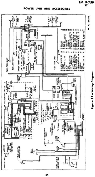
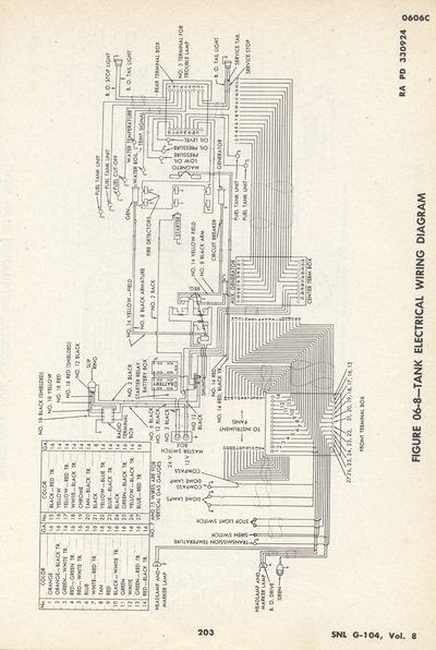
there seems to some question and confusion, about 12 volt VS. 24 volt radios in shermans. perhaps a gallery of schematics will help answer the question.
Gallery
1942
1944
from the volume 8 SNL
1953
at some point the color coded system was dropped and a number system, was instituted, along with this change, the brake lights were deleted. (at least on the A3 shermans). unfortunately the 1954 manual does not include a wire schedule. and I don't believe anyone has ever found a universal schedule to explain all the numbers.
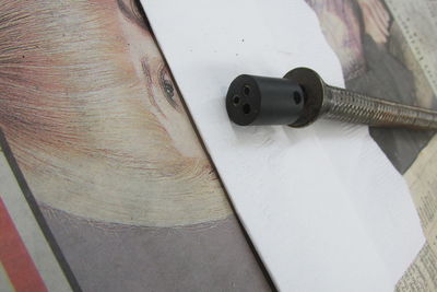
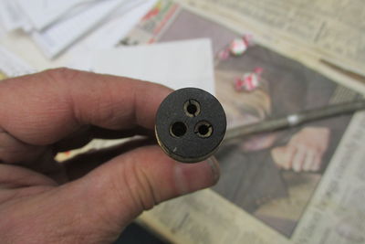
armor harness
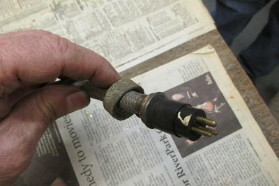
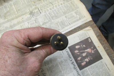
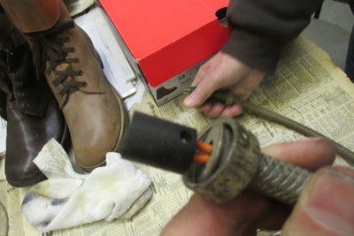
most armored vehicles used woven brass flex conduit with a "garden hose" fitting soldered on the end. the electrical connection was usually a bakelight connector with very small set screws for the wire. and a slide fitting over the set screw section.
References
- TM 9-759 1943, 1944, 1953
- TM TM 11-2748, 45. Installation of Radio and Interphone Equipment in Medium Tank M4A3 or M4A3E2, 75-mm Gun, Wet Stowage; Medium Tank M4A1, M4A2, and M4A3, 105-mm Howitzer, 40 pages. PB 80907 - BSIR 7(1):34; 10/03/47
