Difference between revisions of "SCR-246"
| (4 intermediate revisions by 2 users not shown) | |||
| Line 1: | Line 1: | ||
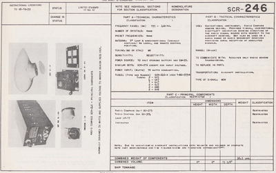
| − | + | Primarily a navigational instrument, Radio Compass SCR·246-A was designed for use in U. S. Army aircraft as a radio compass-type homing device. As such it provides visual, unidirectional, right-left indication showing the direction of the radio signal source with respect to the aircraft heading. For this operation both a loop antenna and a non-directional (usually a vertical) antenna are em- ployed. The equipment may also be used as a radio range or weather broadcast receiver providing aural reception of modulated radio signals. In this connection the non·directional antenna is normally required. However, loop reception is provided as an alternative in weather broadcast reception and is possible and advantageous under certain conditions of charged particle (static) interference if the aircraft is maneuvered so that the transmitting station is to the right or left of the line of flight. Operation of the equipment is accomplished remotely by means of a radio control box which may he mounted in any position convenient to the operator. The frequency range, 195 to 420 kilocycles, is covered in a single band. The general mechanical design is such that the rapid removal of major units can he accomplished for inspection or tactical purposes. | |
| − | + | ||
| + | |||
==Components== | ==Components== | ||
| Line 9: | Line 10: | ||
* [[FT-208]] | * [[FT-208]] | ||
* [[FT-209]] | * [[FT-209]] | ||
| − | * CD-362 | + | * [[CD-362]]*, |
| − | |||
* [[LP-17]], | * [[LP-17]], | ||
* [[I-73]] Ind. | * [[I-73]] Ind. | ||
* [[I-74]] tuning meter | * [[I-74]] tuning meter | ||
* [[MC-187]] chart | * [[MC-187]] chart | ||
| − | == | + | * [[DM-29]] |
| − | * | + | |
| + | ==Tubes== | ||
| + | * [[VT-65]] | ||
| + | * [[VT-86]] | ||
| + | * [[VT-87]] | ||
| + | * [[VT-91]] | ||
| + | * [[VT-93]] | ||
| + | * [[VT-107]] | ||
| − | ;{{ | + | ==Reference Files== |
| + | ;{{cecom_pdf|Scr-246-a radio compass.pdf|Instruction book for radio compass SCR-246-A}} | ||
:Radio Compass SCR-246-A | :Radio Compass SCR-246-A | ||
| − | |||
:: 7 Aug. 1939 | :: 7 Aug. 1939 | ||
| − | + | * TO 08-10-39 | |
| + | |||
| + | |||
| + | ==References== | ||
| + | <references /> | ||
[[Category:Military/Radios]] | [[Category:Military/Radios]] | ||
Latest revision as of 17:57, 25 February 2025
Primarily a navigational instrument, Radio Compass SCR·246-A was designed for use in U. S. Army aircraft as a radio compass-type homing device. As such it provides visual, unidirectional, right-left indication showing the direction of the radio signal source with respect to the aircraft heading. For this operation both a loop antenna and a non-directional (usually a vertical) antenna are em- ployed. The equipment may also be used as a radio range or weather broadcast receiver providing aural reception of modulated radio signals. In this connection the non·directional antenna is normally required. However, loop reception is provided as an alternative in weather broadcast reception and is possible and advantageous under certain conditions of charged particle (static) interference if the aircraft is maneuvered so that the transmitting station is to the right or left of the line of flight. Operation of the equipment is accomplished remotely by means of a radio control box which may he mounted in any position convenient to the operator. The frequency range, 195 to 420 kilocycles, is covered in a single band. The general mechanical design is such that the rapid removal of major units can he accomplished for inspection or tactical purposes.
Contents
Components
- BC-373* LF Radio Compass Rcvr, 12 VDC
- BC-374 Control box
- FT-207
- FT-208
- FT-209
- CD-362*,
- LP-17,
- I-73 Ind.
- I-74 tuning meter
- MC-187 chart
- DM-29
Tubes
Reference Files
 Instruction book for radio compass SCR-246-A[1]
- Radio Compass SCR-246-A
- 7 Aug. 1939
- TO 08-10-39
References
- ↑ Instruction book for radio compass SCR-246-A,
- "US Army Technical Manual Collection,"
- from the CECOM Historical Office archive, Aberdeen Proving Ground, MD.
- CECOM Historical Office
- "US Army Technical Manual Collection,"
