Difference between revisions of "AM-1780~VRC"
Jump to navigation
Jump to search
RadioNerds (talk | contribs) |
RadioNerds (talk | contribs) |
||
| (One intermediate revision by the same user not shown) | |||
| Line 232: | Line 232: | ||
[[Category:Military/Intercoms]] | [[Category:Military/Intercoms]] | ||
| + | {{DISPLAYTITLE:AM-1780/VRC}} | ||
Latest revision as of 00:18, 22 October 2013
Description
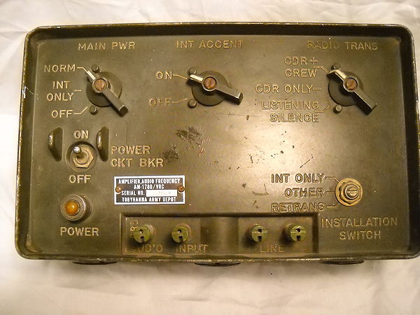
The main junction box for the AN/VIC-1. Provides control of the dc power to the associated crew member control boxes and to the radio system that may be connected to the amplifiers. The amplifiers also amplify and control the audio signals in the intercommunication (intercom) and radio circuits. The AM-1780 also allows connection of 2-wire telephone equipment, or direct 2-wire connection between similarly equipped vehicles via binding post connectors. See sample integrations for other non-standard radios at Integrating the VIC-1 with other equipment.
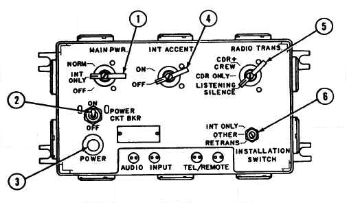
Switch Settings
MAIN POWER (1)
- NORM
- Intercom and all radios configured for remote control power. Requires install mode "OTHER". Power comes in J501 (A radio) jack. Switched power is returned back to A radio on pin D. (May also be sent on J503)
- INT ONLY
- No power provided to radios configured for remote control power.
- OFF
- Intercom and radios configured for remote power turned off. Audio is still enabled and functions in headsets. There is a direct connection from speaker audio to the headsets.
POWER CKT BKR (2)
- ON
- Power is applied to the AM-1780
- OFF
- Circuit breaker has tripped or is turned off. This does not turn off radios that are configured for remote power.
POWER (3)
- Power indicator lamp
INT ACCENT (4)
- ON
- Radio receive volume is reduced when intercom keyed.
- OFF
- Radio receive volume is not reduced when intercom keyed.
RADIO TRANS (5)
- CDR+CREW
- Allows any station to key radio
- CDR ONLY
- Only commander can key radio
- LISTENING SILENCE
- Radio transmission is disabled
INSTALLATION SWITCH (6)
- INT ONLY
- Used when no radios are installed, Power comes in through J508. Radio functions are not active.
- OTHER
- Normal install position for use with radios, Power comes in through J501 (A radio) connection. Radio and PTT functions are active.
- RETRANS
- Same as "OTHER" except retransmission is enabled. Requires C-2299 module be installed.
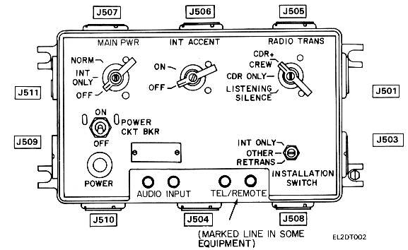
Jack Functions
- J501
- "A" Radio connection. Also supplies power to AM-1780 in "OTHER" mode.
- J503
- "C" radio connection
- J504
- Commander Control Box, Independent of Crew connections (J505-J507)
- J505
- Crew Intercom Control Box, Paralleled with other crew jacks (J505, J506, J507)
- J506
- Crew Intercom Control Box, Paralleled with other crew jacks (J505, J506, J507)
- J507
- Crew Intercom Control Box, Paralleled with other crew jacks (J505, J506, J507)
- J508
- Power connection when in "INT ONLY" mode or C RX radio in "OTHER" mode
- J509
- C-2299 Retransmission connection
- J510
- "B" Radio (RX only) connection
- J511
- C-2299 Retransmission connection
Pinouts
(J501, J22) To Radio Mount
When used between the VIC-1 and the VRC radio
- A - Ground
- B - +25.5 VDC Common
- C - +25.5 VDC, Radio Mount Link
- D - Radio "A" Power Relay Control
- E - NC
- F - NC
- H - Radio "A" Earphones (Variable Audio)
- J - NC
- K - Radio "A" Fixed Audio
- L - NC
- M - NC
- N - NC
- P - NC
- R - NC
- S - Radio "A" Keying (Gnd)
- T - Radio "A" Retrans Control
- U - Radio "A" Mic
- V - NC
(J505, J506, J507, J801, J804, J904) To C-2298 Intercom Box
- A - Ground
- B - "B" Position Earphone Audio
- C - +25.5 VDC
- D - "A" Position Keying
- E - "INT ONLY" Position Mic
- F - "C" Position Keying
- H - "INT" Position Keying
- J - "C" Position Earphone Audio
- K - "A" Position Mic
- L - "ALL" Position Mic
- M - "A" Position Earphone Audio
- N - Telephone Line (C-2297, C-2296)
- P - NC
- R - NC
- S - NC
- T - NC
- U - Telephone Line (C-2297, C-2296)
- V - "C" Position Mic
(J504, CDR1, J801, J804) To C-2298 Intercom Box Commanders Box
- A - Ground
- B - "B" Position Earphone Audio
- C - +25.5 VDC
- D - "A" Position Keying
- E - "INT ONLY" Position Mic
- F - "C" Position Keying
- H - "INT" Position Keying
- J - "C" Position Earphone Audio
- K - "A" Position Mic
- L - "ALL" Position Mic
- M - "A" Position Earphone Audio
- N - NC
- P - NC
- R - NC
- S - NC
- T - NC
- U - NC
- V - "C" Position Mic
(J511, J22) To Retrans
- A - Ground
- B - NC
- C - +25.5 VDC
- D - NC
- E - NC
- F - NC
- H - NC
- J - NC
- K - Radio "A" Fixed Audio
- L - Radio "A" Keying Retrans
- M - NC
- N - NC
- P - NC
- R - NC
- S - Radio "A" Keying
- T - Radio "A" Retrans Control
- U - Radio "A" Mic
- V - NC
(J510, J121) To Receiver B
- A - Ground
- B - NC
- C - NC
- D - NC
- E - NC
- F - NC
- H - Receiver "B" Variable Audio
- J - NC
- K - Receiver "B" Fixed Audio
(J508) To Power or Receiver C
- A - Ground
- B - +25.5 VDC
- C - Receiver "C" Fixed Audio
- D - Receiver "C" Variable Audio
Related Files
- OPERATOR'S AND ORGANIZATIONAL MAINTENANCE MANUAL
- INTERCOMMUNICATION SET AN/VIC-1(V) (NSN 5830-00-856-3273)
- CONTROL, INTERCOMMUNICATION SETS
- C-10456/VRC (NSN 5830-01-082-0804)
- C-10680/VRC
- AMPLIFIER, AUDIO FREQUENCY
- AM-7046/VRC
- 15 January 1986
- Direct Support Maintenance
- INTERCOMMUNICATION SET AN/VIC-1(V) (NSN 5830-00-856-3273)
- 15 September 1986
AM-1780B
- UNIT, DIRECT SUPPORT AND GENERAL SUPPORT MAINTENANCE
- REPAIR PARTS AND SPECIAL TOOLS LIST
- AMPLIFIER, AUDIO FREQUENCY
- AM-1780B/VRC (NSN 5895-01-284-3057)
- 1 NOVEMBER 1997
- DIRECT AND GENERAL SUPPORT MAINTENANCE MANUAL
- AUDIO FREQUENCY AMPLIFIER
- AM-1780B/VRC (NSN 5895-01-284-3057)
- 1 MAY 1995


