Difference between revisions of "LS-671~VRC"
RadioNerds (talk | contribs) |
RadioNerds (talk | contribs) |
||
| (93 intermediate revisions by 2 users not shown) | |||
| Line 1: | Line 1: | ||
| − | =Overview= | + | ==Overview== |
| − | This is a simple speaker that is used with the SINCGARS series radios. This speaker can be adapted for use with other systems. | + | This is a simple speaker that is used with the SINCGARS series radios. This speaker can be adapted for use with other systems. This is an amplified speaker and will need 12 or 24 volts to function properly. |
| + | |||
| + | |||
| + | {{Template:Verified}} | ||
| + | |||
[[File:LS-671.JPG|400px]] | [[File:LS-671.JPG|400px]] | ||
| + | <gallery widths=100px heights=100px perrow=5> | ||
| + | File:LS-671-1.JPG | ||
| + | File:LS-671-2.jpg | ||
| + | </gallery> | ||
| − | + | ==Usage== | |
| − | =Usage= | ||
[[File:LS-671-3.png]] | [[File:LS-671-3.png]] | ||
| Line 27: | Line 34: | ||
| + | ==Parts View== | ||
| − | + | [[File:ls-671-exploded_view.png|500px]] | |
| − | + | #BOLT, MACHINE | |
| − | + | #WASHER, LOCK | |
| − | + | #WASHER, FLAT | |
| − | + | #CIRCUIT BREAKER | |
| − | + | #COVER, LOUDSPEAKER | |
| − | + | #SCREW, TAPPING | |
| − | + | #SCREW, SEAL | |
| − | + | #LAMP HOLDER | |
| − | + | #PLATE, IDENTIFICATION | |
| − | + | #CASE, LOUDSPEAKER | |
| − | + | #KNOB | |
| − | + | #CASE, LOUDSPEAKER | |
| − | + | #LOUDSPEAKER, CRYSTAL | |
| − | + | #LENS, LIGHT | |
| − | + | #LAMP, INCANDESCENT | |
| + | #PLATE, MOUNTING, LAMP | ||
| + | ==Schematics== | ||
| + | ;General Schematic and block Diagram | ||
| + | [[File:lS-671-schematic.png|400px]] | ||
| − | == | + | |
| + | ;Schematic of the interhook cable | ||
| + | [[File:TM-11-5820-890-20-1 148 1.jpeg|400px]] | ||
| + | |||
| + | |||
| + | ;Hooking to the PRC 77/25 Via the power jack | ||
| + | [[File:LS671PRC77.JPG|400px]] | ||
| + | |||
| + | |||
| + | :Block Diagram | ||
| + | [[File:LS671.png|400px]] | ||
| + | |||
| + | ==Pinouts== | ||
| + | |||
| + | These pinouts state 24V however if you feed the speaker with 12v as seen in some hookups, the values below will of course be 12v. | ||
| + | |||
| + | {|class="wikitable" | ||
| + | |'''Pin''' | ||
| + | |'''Description''' | ||
| + | |'''Notes''' | ||
| + | |- | ||
| + | | align=center| '''A''' | ||
| + | |nowrap|Ground | ||
| + | |This is used for both the audio ground and a power ground | ||
| + | |- | ||
| + | |align=center| '''B''' | ||
| + | |nowrap|Unswitched 24v | ||
| + | |(B + Line) This is used as a constant 24v source into the speaker, to use the speaker this is required as a minumum | ||
| + | |- | ||
| + | |align=center| '''C''' | ||
| + | |nowrap|Switched 24V in | ||
| + | |(Relay control line) This allows 24v to be supplied to PIN D when the power switch is turned on | ||
| + | |- | ||
| + | |align=center| '''D''' | ||
| + | |nowrap|Switched 24V out | ||
| + | |(Power Relay Control Line) PIN C is is connection to this pin, when the power switch is turned on | ||
| + | |- | ||
| + | |align=center| '''E''' | ||
| + | |nowrap|Test Point speaker - | ||
| + | |This is used to test the speaker, bypassing the audio circuits | ||
| + | |- | ||
| + | |align=center| '''F''' | ||
| + | |nowrap|Test Point. speaker + | ||
| + | |This is used to test the speaker, bypassing the audio circuits | ||
| + | |- | ||
| + | |align=center| '''J''' | ||
| + | |nowrap|Remote PTT | ||
| + | |When the PTT key on the Microphone connected to J1 is pressed, this pin connects to Ground PIN A. | ||
| + | |- | ||
| + | |align=center| '''K''' | ||
| + | |nowrap|RX Audio in | ||
| + | |receive audio source is hooked here, this should be isolated with a transformer if a 12volt radio is used | ||
| + | |- | ||
| + | |align=center| '''S''' | ||
| + | |nowrap|Routed to PIN A | ||
| + | |This is usually the PTT line in VIC1 configurations, since this is routed the Ground, hooking this to a VIC1 using the wrong cable will cause the speaker to key the radio. | ||
| + | |- | ||
| + | |align=center| '''U''' | ||
| + | |nowrap|Transmit Audio | ||
| + | |Audio input from the microphone | ||
| + | |} | ||
| + | |||
| + | ==Hooking up as a simple speaker== | ||
| + | Properly interfacing this speaker into 12volt radio, will require the use of an isolation circuit to prevent the 24volt system from harming the 12volt radios. example interfaces can be seen in [[Integrating_with_other_equipment| integrating with other equipment]]. There are some limitations listed in each of the methods detailed below, and most of them are due to the reduced input voltage. Here is a synopsis of the issues. | ||
| + | |||
| + | ;Known Issues with 12volt in general | ||
| + | :Light bulb dim - wrong voltage, replace bulb | ||
| + | :push volume control doesn't mute speaker | ||
| + | :audio output lower | ||
| + | :minor hum or buzz in some systems, but tolerable | ||
| + | |||
| + | |||
| + | |||
| + | ==Simple Hookup with a 3.5mm audio jack== | ||
| + | Generally speaking you can hook the "audio GND" line to the "ring" of an audio jack and the "Audio in" to the "tip" | ||
| + | |||
| + | [[File:Audio plug.png]] | ||
| + | |||
| + | ==24 Volt Vehicle / 12 Volt Radio (amplified)== | ||
| + | The use of the transformer is to isolate the 24volt speaker from the 12volt audio source. Without this you run the risk of exposing the 12volt radio to 24volt source... not a good idea.. | ||
| + | |||
| + | ====Known Limitations==== | ||
| + | None Found | ||
[[File:LS-671 RX Only.png|600px]] | [[File:LS-671 RX Only.png|600px]] | ||
| − | == | + | ==12 Volt Vehicle / 12 volt Radio (amplified)== |
| − | + | If you choose to use 12Volt for the power to the speaker the transformer is not required. | |
| − | File:LS-671-1. | + | |
| − | File:LS-671- | + | ====Known Limitations==== |
| − | File: | + | These are differences in operation we noticed when using this with 12volts, these are confirmed to work fine if you use 24 volts. |
| − | + | ;The light bulb will be dim, | |
| + | :The voltage is 1/2 of the rating of the bulb, it will be dim. | ||
| + | :If you want to replace it, the part number is: 12 Volt: GE 394 (replaces the stock 24 Volt bulb: OL-387 or GE 387) | ||
| + | ;Pushing the volume control down doesn't mute the radio speaker | ||
| + | :(not sure why yet) | ||
| + | |||
| + | |||
| + | [[File:LS-671 RX Only - 12volt.png|600px]] | ||
| + | |||
| + | |||
| + | |||
| + | |||
| + | ==Hooking up as a simple speaker (un-amplified)== | ||
| + | you can also hook this speaker up in a way that bypasses all the circuits. These points are used to test the speaker. This will likely sound "tinny" but it will work. | ||
| + | |||
| + | ====Known Limitations==== | ||
| + | ;None of the controls function | ||
| + | :This is because we bypassed everything and went directly to the speaker | ||
| + | |||
| + | |||
| + | [[File:LS-671 RX-not_amplified.png|600px]] | ||
| + | |||
| + | |||
| + | |||
| + | ==Hooking up for full PTT, transmit and receive audio for non-military radios== | ||
| + | This method will allow you to have full Transmit (TX) and Receive (RX) from any 12volt radio. | ||
| + | |||
| + | NOTE: do not hookup the ground to PIN S or feedback on the transmit audio will occur. | ||
| + | |||
| + | ====Known Limitations==== | ||
| + | These are differences in operation we noticed when using this with 12volts, these are confirmed to work fine if you use 24 volts. | ||
| + | ;The light bulb will be dim, | ||
| + | :The voltage is 1/2 of the rating of the bulb, it will be dim. | ||
| + | :If you want to replace it, the part number is: 12 Volt: GE 394 (replaces the stock 24 Volt bulb: OL-387 or GE 387) | ||
| + | ;Pushing the volume control down doesn't mute the radio speaker | ||
| + | :(not sure why yet) | ||
| + | ;Low TX output audio | ||
| + | :This is due to the reduced voltage, working on a solution | ||
| + | |||
| + | |||
| + | [[File:LS-671 TX RX.png|600px]] | ||
| + | |||
| + | In my system i was getting a notable buzz on the transmit audio, this is was due to some bad connections . Upon testing the signal report was clear, but audio was low. I expected that though, i need to adjust this internally by some mods. Still Experimenting... | ||
| + | |||
| + | |||
| + | |||
| + | |||
| + | ==Using the LS-671 to remotely Power On/Off any 12volt radio== | ||
| + | The LS-671 has some interesting features that allow it to remotely turn on/off radios. for example, mounting a CB, GMRS, AM/FM under the seat and using the LS-671 Power switch to turn on and off the other radio. Of course you would have remote volume control receive audio and transmit functions... | ||
| + | |||
| + | ====Features==== | ||
| + | :Remote On/Off of the radio by the from power switch on the speaker | ||
| + | :Volume control for RX | ||
| + | :Transmit for TX | ||
| + | |||
| + | |||
| + | ====Known Limitations==== | ||
| + | ;Same as above for the other hookup methods | ||
| + | ;if you leave the speaker on, and manually turn off the radio, the speaker will still draw from the battery. (even in military radios it does this) | ||
| + | |||
| + | |||
| + | This uses a simple 12volt relay to connect the 12volt power line of the radio, this is accomplished by Pin D of the Ls-671 where voltage is applied when the speaker is turned on. You need to use a relay because its unlikely the speaker will be able to handle the power draw of the radio (especially in transmit). You can use any 12volt relay, the one listed is a SPDT but i also used a DPDT from radio shack (OMI-SS-212D) | ||
| + | |||
| + | [[File:LS-671_tx_rx_with_relay.png|600px]] | ||
| + | |||
| + | |||
| + | |||
| + | |||
| + | ==I Think that is all this speaker can do, anything else?== | ||
| + | happy hacking :-) | ||
| + | |||
| + | |||
| + | ==Reference Files== | ||
| + | ;{{pdf|TB_11-5820-890-10-14.pdf|TB 11-5820-890-10-14}} | ||
| + | :OPERATION OF LS-671 LOUDSPEAKER WITH SINCGARS RADIO SETS | ||
| + | ::1 April 1993 | ||
| + | |||
| + | |||
| + | ;{{pdf|TM_11-5820-890-30-4_excerpt_ls671.pdf|Excerpt of TM 11-5820-890-30-4 Related to LS-671}} | ||
| + | |||
| + | [[Category:Military/Speakers]] | ||
| + | [[Category:Military/Integration Projects]] | ||
| + | {{DISPLAYTITLE:LS-671/VRC}} | ||
Latest revision as of 14:47, 4 March 2015
Contents
- 1 Overview
- 2 Usage
- 3 Parts View
- 4 Schematics
- 5 Pinouts
- 6 Hooking up as a simple speaker
- 7 Simple Hookup with a 3.5mm audio jack
- 8 24 Volt Vehicle / 12 Volt Radio (amplified)
- 9 12 Volt Vehicle / 12 volt Radio (amplified)
- 10 Hooking up as a simple speaker (un-amplified)
- 11 Hooking up for full PTT, transmit and receive audio for non-military radios
- 12 Using the LS-671 to remotely Power On/Off any 12volt radio
- 13 I Think that is all this speaker can do, anything else?
- 14 Reference Files
Overview
This is a simple speaker that is used with the SINCGARS series radios. This speaker can be adapted for use with other systems. This is an amplified speaker and will need 12 or 24 volts to function properly.
Usage
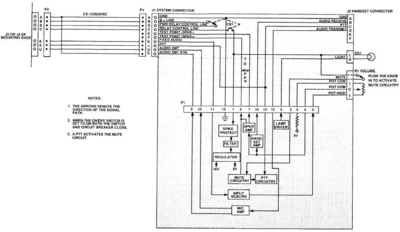
- (CB1) Power ON/OFF Switch
- On Off switch for the powered speaker and accessories connected via pin D
- (J1) Cable Connector
- interface cable connection
- (J2) Handset Connector
- H250 Style handset Microphone connects here
- (DS1) Power Indicator Lamp
- Lamp indicates power is on in the speaker. This can be dimmed by turning the outer housing. The housing can also unscreww to replace the lamp. Uses the common bulb seen on VIC1-Vic4 and many Radios VRC Series and later
- (R1) Volume Control
- This controls the volume for both the Handset connected to J2 and the speaker itself.
- Pushing the knob in, shuts off the external speaker and also provides volume control to the handset mic.
- Pulling out the knob, enables the external speaker and controls its volume.
Parts View
- BOLT, MACHINE
- WASHER, LOCK
- WASHER, FLAT
- CIRCUIT BREAKER
- COVER, LOUDSPEAKER
- SCREW, TAPPING
- SCREW, SEAL
- LAMP HOLDER
- PLATE, IDENTIFICATION
- CASE, LOUDSPEAKER
- KNOB
- CASE, LOUDSPEAKER
- LOUDSPEAKER, CRYSTAL
- LENS, LIGHT
- LAMP, INCANDESCENT
- PLATE, MOUNTING, LAMP
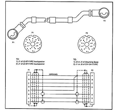
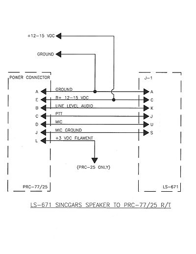
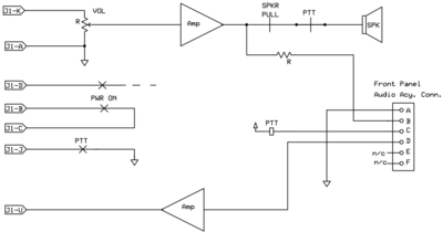
Schematics
- General Schematic and block Diagram
- Schematic of the interhook cable
- Hooking to the PRC 77/25 Via the power jack
- Block Diagram
Pinouts
These pinouts state 24V however if you feed the speaker with 12v as seen in some hookups, the values below will of course be 12v.
| Pin | Description | Notes |
| A | Ground | This is used for both the audio ground and a power ground |
| B | Unswitched 24v | (B + Line) This is used as a constant 24v source into the speaker, to use the speaker this is required as a minumum |
| C | Switched 24V in | (Relay control line) This allows 24v to be supplied to PIN D when the power switch is turned on |
| D | Switched 24V out | (Power Relay Control Line) PIN C is is connection to this pin, when the power switch is turned on |
| E | Test Point speaker - | This is used to test the speaker, bypassing the audio circuits |
| F | Test Point. speaker + | This is used to test the speaker, bypassing the audio circuits |
| J | Remote PTT | When the PTT key on the Microphone connected to J1 is pressed, this pin connects to Ground PIN A. |
| K | RX Audio in | receive audio source is hooked here, this should be isolated with a transformer if a 12volt radio is used |
| S | Routed to PIN A | This is usually the PTT line in VIC1 configurations, since this is routed the Ground, hooking this to a VIC1 using the wrong cable will cause the speaker to key the radio. |
| U | Transmit Audio | Audio input from the microphone |
Hooking up as a simple speaker
Properly interfacing this speaker into 12volt radio, will require the use of an isolation circuit to prevent the 24volt system from harming the 12volt radios. example interfaces can be seen in integrating with other equipment. There are some limitations listed in each of the methods detailed below, and most of them are due to the reduced input voltage. Here is a synopsis of the issues.
- Known Issues with 12volt in general
- Light bulb dim - wrong voltage, replace bulb
- push volume control doesn't mute speaker
- audio output lower
- minor hum or buzz in some systems, but tolerable
Simple Hookup with a 3.5mm audio jack
Generally speaking you can hook the "audio GND" line to the "ring" of an audio jack and the "Audio in" to the "tip"
24 Volt Vehicle / 12 Volt Radio (amplified)
The use of the transformer is to isolate the 24volt speaker from the 12volt audio source. Without this you run the risk of exposing the 12volt radio to 24volt source... not a good idea..
Known Limitations
None Found
12 Volt Vehicle / 12 volt Radio (amplified)
If you choose to use 12Volt for the power to the speaker the transformer is not required.
Known Limitations
These are differences in operation we noticed when using this with 12volts, these are confirmed to work fine if you use 24 volts.
- The light bulb will be dim,
- The voltage is 1/2 of the rating of the bulb, it will be dim.
- If you want to replace it, the part number is: 12 Volt: GE 394 (replaces the stock 24 Volt bulb: OL-387 or GE 387)
- Pushing the volume control down doesn't mute the radio speaker
- (not sure why yet)
Hooking up as a simple speaker (un-amplified)
you can also hook this speaker up in a way that bypasses all the circuits. These points are used to test the speaker. This will likely sound "tinny" but it will work.
Known Limitations
- None of the controls function
- This is because we bypassed everything and went directly to the speaker
Hooking up for full PTT, transmit and receive audio for non-military radios
This method will allow you to have full Transmit (TX) and Receive (RX) from any 12volt radio.
NOTE: do not hookup the ground to PIN S or feedback on the transmit audio will occur.
Known Limitations
These are differences in operation we noticed when using this with 12volts, these are confirmed to work fine if you use 24 volts.
- The light bulb will be dim,
- The voltage is 1/2 of the rating of the bulb, it will be dim.
- If you want to replace it, the part number is: 12 Volt: GE 394 (replaces the stock 24 Volt bulb: OL-387 or GE 387)
- Pushing the volume control down doesn't mute the radio speaker
- (not sure why yet)
- Low TX output audio
- This is due to the reduced voltage, working on a solution
In my system i was getting a notable buzz on the transmit audio, this is was due to some bad connections . Upon testing the signal report was clear, but audio was low. I expected that though, i need to adjust this internally by some mods. Still Experimenting...
Using the LS-671 to remotely Power On/Off any 12volt radio
The LS-671 has some interesting features that allow it to remotely turn on/off radios. for example, mounting a CB, GMRS, AM/FM under the seat and using the LS-671 Power switch to turn on and off the other radio. Of course you would have remote volume control receive audio and transmit functions...
Features
- Remote On/Off of the radio by the from power switch on the speaker
- Volume control for RX
- Transmit for TX
Known Limitations
- Same as above for the other hookup methods
- if you leave the speaker on, and manually turn off the radio, the speaker will still draw from the battery. (even in military radios it does this)
This uses a simple 12volt relay to connect the 12volt power line of the radio, this is accomplished by Pin D of the Ls-671 where voltage is applied when the speaker is turned on. You need to use a relay because its unlikely the speaker will be able to handle the power draw of the radio (especially in transmit). You can use any 12volt relay, the one listed is a SPDT but i also used a DPDT from radio shack (OMI-SS-212D)
I Think that is all this speaker can do, anything else?
happy hacking :-)
Reference Files
- OPERATION OF LS-671 LOUDSPEAKER WITH SINCGARS RADIO SETS
- 1 April 1993


