Difference between revisions of "AN~URC-32"
RadioNerds (talk | contribs) |
RadioNerds (talk | contribs) |
||
| (9 intermediate revisions by the same user not shown) | |||
| Line 1: | Line 1: | ||
| + | =Description= | ||
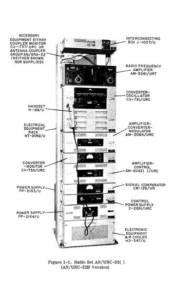
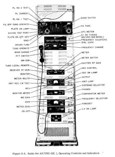
| + | Radio transceiver AN/URC-32 is a manually operated radio communication equipment for operation in the 2-30 mHz range. With a power output of 500 watts, this transceiver is capable of transmitting signals over long distances. It is designed for single-sideband transmission and reception on upper sideband (USB), lower sideband (LSB), or the two independent sidebands simultaneously, with separate AF and IF channels for each sideband. In addition to SSB operation, provisions are included for compatible a-m (carrier plus upper sideband), CW, or frequency shift keying (fsk). The fsk mode of operation is used for sending radio teletype (RATT) and facsimile (FAX) signals. | ||
| + | The frequency range of 2 to 30 mc is covered in four bands. The desired operating frequency is selected in 1 kHz increments (0.1 kHz on B model) on a direct-reading frequency counter. Frequency accuracy and stability are controlled by a self-contained frequency standard. Provisions also are made for using an external frequency standard. Because of its versatility and power, the AN/URC-32 is installed on most Navy ships having a requirement for communicating at long distances. | ||
| + | |||
| + | |||
| + | [[File:AN URC-32.jpg|400px]] | ||
| + | [[File:AN URC-32_controls.jpg|400px]] | ||
| + | |||
| + | |||
| + | ==Cross Reference Chart== | ||
| + | The URC-32 is essentially a Collins KWT-6, the following chart describes the individual components between the Collins and Military designations. | ||
| + | |||
| + | {| class="wikitable" style="width:90%; border:2px solid black;" | ||
| + | !colspan="3"| Collins to Military Component Designations | ||
| + | |- | ||
| + | ! scope="col" |Description | ||
| + | ! scope="col" |Collins | ||
| + | ! scope="col" |Military | ||
| + | |- | ||
| + | |Transceiver Power Amplifier | ||
| + | |367A-3 | ||
| + | |AM-2061/URT | ||
| + | |- | ||
| + | |Frequency Generator | ||
| + | |786E-1 | ||
| + | |CV-731/URC | ||
| + | |- | ||
| + | |Sideband Generator | ||
| + | |786F-1 | ||
| + | |AM-2061/URC | ||
| + | |- | ||
| + | |Audio and Control Unit | ||
| + | |159B-1 | ||
| + | |AM-2062/URC | ||
| + | |- | ||
| + | |Audio and Control Unit | ||
| + | |159B-2 | ||
| + | |AM-2062A/URC | ||
| + | |- | ||
| + | |High Voltage Power Supply | ||
| + | |428B-1 | ||
| + | |PP-2153/U | ||
| + | |- | ||
| + | |Low Voltage Power Supply | ||
| + | |429B-1 | ||
| + | |PP-2154/U | ||
| + | |- | ||
| + | |Dynamic Handset | ||
| + | |Dynamic Handset | ||
| + | |H-169/U and Cord Assembly CX-1846A/U | ||
| + | |- | ||
| + | |Handset Adaptor | ||
| + | |Handset Adaptor | ||
| + | |Control Power Supply | ||
| + | C-2691/URC | ||
| + | |- | ||
| + | |Frequency Comparator | ||
| + | |54Q-1 | ||
| + | |Signal Comparator | ||
| + | CM-126/UR | ||
| + | |- | ||
| + | |CW and FSK Unit | ||
| + | |CW and FSK Unit | ||
| + | |Converter Monitor | ||
| + | CV-730/URC | ||
| + | |- | ||
| + | |Dummy Antenna | ||
| + | |172J-1 | ||
| + | |Electrical Dummy Load | ||
| + | DA-218/U | ||
| + | |- | ||
| + | |Junction Box | ||
| + | |153H-3 | ||
| + | |Interconnecting Box | ||
| + | J-1007/U | ||
| + | |- | ||
| + | |Blower | ||
| + | |199G-3 | ||
| + | |Electronic Equipment Air Cooler | ||
| + | HD-347/U | ||
| + | |- | ||
| + | |Mounting Rack and Shock Mount | ||
| + | |Mounting Rack and Shock Mount | ||
| + | |Electrical Equipment Rack | ||
| + | MT-2092/U | ||
| + | |- | ||
| + | |} | ||
| + | |||
| + | |||
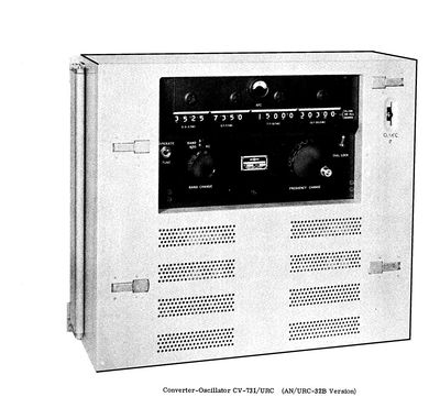
| + | [[File:CV-731 URC 8751786219 l.jpg|400px]] | ||
| + | |||
| + | ==Military HD-347/U Electronic Equipment Air Cooler (Collins Blower 1990-3)== | ||
| + | Collins Blower 1990-3, shown in figure 20, is a centrifugal blower capable of delivering 125 cfm of air at a pressure equivalent to 1.83 inches of water. The 1990-3 includes a double-pole, single-throw switch which is actuated by air pressure. The switch contacts are used as interlocks for the primary power to the system. A block diagram of the 1990-3 is shown in figure 21. The unit mounts in a standard 19-inch open-type rack. Cooling air is supplied to the units mounted in the rack through a central air duct, All power and control connections are made through an 8-pin connector located on the top of the 1990-3. Access to components is obtained by removing the front cover and air filter. | ||
| + | |||
| + | ===Technical characteristics=== | ||
| + | ;VOLTAGE SOURCE: | ||
| + | :115/230 Volts AC, 50 to 60 cps. | ||
| + | ;POWER INPUT: | ||
| + | :215 watts at 1.0-in. water gauge pressure. | ||
| + | ;OUTPUT CAPACITY: | ||
| + | :125 cfm at 1.83-in. water gauge static pressure. | ||
| + | ;DIMENSIONS: | ||
| + | :8-7/8 in. high by 11-1/4 in. deep by 19 in, wide. | ||
| + | ;WEIGHT: | ||
| + | :22 pounds. | ||
| + | ;REQUIRED RACK SPACE: | ||
| + | :8-7/8 in, | ||
| + | |||
| + | |||
| + | ====Blower Bearing Replacement==== | ||
| + | On of the most common issues with the Cooling unit is the bearings become noisy. They are very simple to replace. The Bartlett Bearing Part number for this part is "WC87038" 2 are required. As of Dec 2016 they were $23.00 each. As an alternative you can use the ultra common 608 bearing which is a common skate bearing and cost under $4.00. it is thinner than the original, but will work perfectly fine. Some shimming may be required. | ||
| − | |||
[[Category:Military/Radios]] | [[Category:Military/Radios]] | ||
{{DISPLAYTITLE:AN/URC-32}} | {{DISPLAYTITLE:AN/URC-32}} | ||
Latest revision as of 18:52, 13 December 2016
Contents
Description
Radio transceiver AN/URC-32 is a manually operated radio communication equipment for operation in the 2-30 mHz range. With a power output of 500 watts, this transceiver is capable of transmitting signals over long distances. It is designed for single-sideband transmission and reception on upper sideband (USB), lower sideband (LSB), or the two independent sidebands simultaneously, with separate AF and IF channels for each sideband. In addition to SSB operation, provisions are included for compatible a-m (carrier plus upper sideband), CW, or frequency shift keying (fsk). The fsk mode of operation is used for sending radio teletype (RATT) and facsimile (FAX) signals. The frequency range of 2 to 30 mc is covered in four bands. The desired operating frequency is selected in 1 kHz increments (0.1 kHz on B model) on a direct-reading frequency counter. Frequency accuracy and stability are controlled by a self-contained frequency standard. Provisions also are made for using an external frequency standard. Because of its versatility and power, the AN/URC-32 is installed on most Navy ships having a requirement for communicating at long distances.
Cross Reference Chart
The URC-32 is essentially a Collins KWT-6, the following chart describes the individual components between the Collins and Military designations.
| Collins to Military Component Designations | ||
|---|---|---|
| Description | Collins | Military |
| Transceiver Power Amplifier | 367A-3 | AM-2061/URT |
| Frequency Generator | 786E-1 | CV-731/URC |
| Sideband Generator | 786F-1 | AM-2061/URC |
| Audio and Control Unit | 159B-1 | AM-2062/URC |
| Audio and Control Unit | 159B-2 | AM-2062A/URC |
| High Voltage Power Supply | 428B-1 | PP-2153/U |
| Low Voltage Power Supply | 429B-1 | PP-2154/U |
| Dynamic Handset | Dynamic Handset | H-169/U and Cord Assembly CX-1846A/U |
| Handset Adaptor | Handset Adaptor | Control Power Supply
C-2691/URC |
| Frequency Comparator | 54Q-1 | Signal Comparator
CM-126/UR |
| CW and FSK Unit | CW and FSK Unit | Converter Monitor
CV-730/URC |
| Dummy Antenna | 172J-1 | Electrical Dummy Load
DA-218/U |
| Junction Box | 153H-3 | Interconnecting Box
J-1007/U |
| Blower | 199G-3 | Electronic Equipment Air Cooler
HD-347/U |
| Mounting Rack and Shock Mount | Mounting Rack and Shock Mount | Electrical Equipment Rack
MT-2092/U |
Military HD-347/U Electronic Equipment Air Cooler (Collins Blower 1990-3)
Collins Blower 1990-3, shown in figure 20, is a centrifugal blower capable of delivering 125 cfm of air at a pressure equivalent to 1.83 inches of water. The 1990-3 includes a double-pole, single-throw switch which is actuated by air pressure. The switch contacts are used as interlocks for the primary power to the system. A block diagram of the 1990-3 is shown in figure 21. The unit mounts in a standard 19-inch open-type rack. Cooling air is supplied to the units mounted in the rack through a central air duct, All power and control connections are made through an 8-pin connector located on the top of the 1990-3. Access to components is obtained by removing the front cover and air filter.
Technical characteristics
- VOLTAGE SOURCE
- 115/230 Volts AC, 50 to 60 cps.
- POWER INPUT
- 215 watts at 1.0-in. water gauge pressure.
- OUTPUT CAPACITY
- 125 cfm at 1.83-in. water gauge static pressure.
- DIMENSIONS
- 8-7/8 in. high by 11-1/4 in. deep by 19 in, wide.
- WEIGHT
- 22 pounds.
- REQUIRED RACK SPACE
- 8-7/8 in,
Blower Bearing Replacement
On of the most common issues with the Cooling unit is the bearings become noisy. They are very simple to replace. The Bartlett Bearing Part number for this part is "WC87038" 2 are required. As of Dec 2016 they were $23.00 each. As an alternative you can use the ultra common 608 bearing which is a common skate bearing and cost under $4.00. it is thinner than the original, but will work perfectly fine. Some shimming may be required.


