Difference between revisions of "Raytheon RA-1000"
Jump to navigation
Jump to search
RadioNerds (talk | contribs) (Created page with "Recently i have been asked to participate in the restoration of an old AM broadcast transmitter... a Raytheon RA-1000") |
RadioNerds (talk | contribs) |
||
| (27 intermediate revisions by the same user not shown) | |||
| Line 1: | Line 1: | ||
| − | + | =Raytheon RA-1000-A Broadcast Transmitter= | |
| + | |||
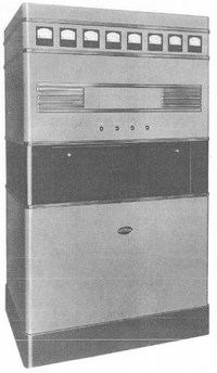
| + | [[File:ra-1000.png|200px]] | ||
| + | |||
| + | |||
| + | ==Specifications== | ||
| + | |||
| + | ===Electrical=== | ||
| + | ;Emission Type | ||
| + | :Telephone | ||
| + | |||
| + | ;Carrier Output | ||
| + | :1000 Watts | ||
| + | |||
| + | ;Frequency Range | ||
| + | :540-1600 kHz | ||
| + | |||
| + | ;Power Supply | ||
| + | :210-230 Volts 5-60 cycles | ||
| + | :3 wire single phase | ||
| + | |||
| + | ===Mechanical=== | ||
| + | ;Height | ||
| + | :7 Ft (84 Inches) | ||
| + | |||
| + | ;Weight | ||
| + | :2450 Pounds | ||
| + | |||
| + | ==Manuals== | ||
| + | {{pdf|raytheon_RA-1000-A_manual.pdf|RA-1000-A Manual}} | ||
| + | |||
| + | |||
| + | |||
| + | |||
| + | ==Cabinet Pictures== | ||
| + | |||
| + | <gallery widths=100px heights=100px perrow=5> | ||
| + | File:ra-1000.png | ||
| + | File:ra-1000-front.png | ||
| + | File:ra-1000-back.png | ||
| + | File:ra-1000-bottom.png | ||
| + | File:ra-1000-side1.png | ||
| + | </gallery> | ||
| + | |||
| + | ==Sections== | ||
| + | |||
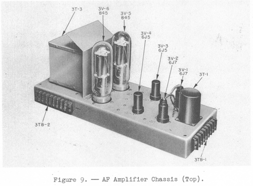
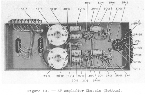
| + | ===AF Amplifier Chassis=== | ||
| + | [[File:af_amp_top.png|500px]] | ||
| + | [[File:af_amp_bottom.png|500px]] | ||
| + | |||
| + | |||
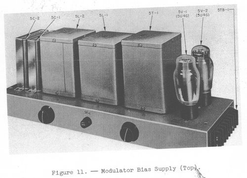
| + | ===Modulator Bias Supply=== | ||
| + | [[File:mod_bias_supply_top.png|500px]] | ||
| + | [[File:mod_bias_supply_bottom.png|500px]] | ||
| + | |||
| + | ;Restoration Photos | ||
| + | <gallery widths=100px heights=100px perrow=10> | ||
| + | File:5R-3.JPG | ||
| + | </gallery> | ||
| + | |||
| + | ===Exciter Chassis=== | ||
| + | [[File:exciter_top.png|500px]] | ||
| + | [[File:exciter_bottom.png|500px]] | ||
| + | |||
| + | |||
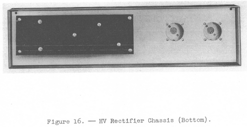
| + | ===HV Rectifier Chassis=== | ||
| + | [[File:hv_rectifier_top.png|500px]] | ||
| + | [[File:hv_rectifier_bottom.png|500px]] | ||
| + | |||
| + | |||
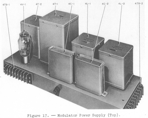
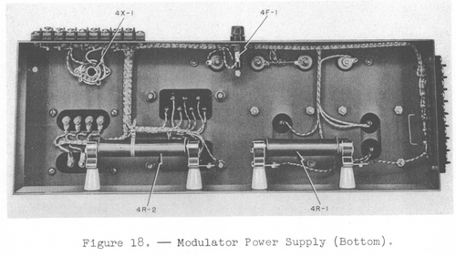
| + | ===Modulator Power Supply=== | ||
| + | [[File:mod_power_supply_top.png|500px]] | ||
| + | [[File:mod_power_supply_bottom.png|500px]] | ||
| + | |||
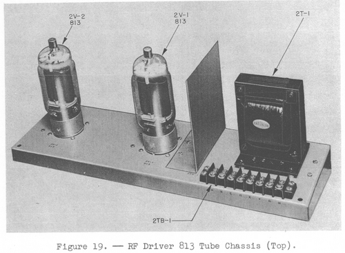
| + | ===RF Driver 813 Tube Chassis=== | ||
| + | [[File:rf_driver_813_top.png|500px]] | ||
| + | [[File:rf_driver_813_bottom.png|500px]] | ||
| + | |||
| + | |||
| + | ===Pre-restoration Photos=== | ||
| + | <gallery widths=100px heights=100px perrow=10> | ||
| + | File:DSC_0367.JPG | ||
| + | File:DSC_0281.JPG | ||
| + | File:DSC_0300.JPG | ||
| + | File:DSC_0342.JPG | ||
| + | File:DSC_0366.JPG | ||
| + | File:DSC_0346.JPG | ||
| + | File:DSC_0310.JPG | ||
| + | File:DSC_0328.JPG | ||
| + | File:DSC_0322.JPG | ||
| + | File:DSC_0345.JPG | ||
| + | File:DSC_0332.JPG | ||
| + | File:DSC_0298.JPG | ||
| + | File:DSC_0337.JPG | ||
| + | File:DSC_0278.JPG | ||
| + | File:DSC_0287.JPG | ||
| + | File:DSC_0319.JPG | ||
| + | File:DSC_0294.JPG | ||
| + | File:DSC_0329.JPG | ||
| + | File:DSC_0317.JPG | ||
| + | File:DSC_0316.JPG | ||
| + | File:DSC_0290.JPG | ||
| + | File:DSC_0280.JPG | ||
| + | File:DSC_0276.JPG | ||
| + | File:DSC_0326.JPG | ||
| + | File:DSC_0348.JPG | ||
| + | File:DSC_0338.JPG | ||
| + | File:DSC_0318.JPG | ||
| + | File:DSC_0351.JPG | ||
| + | File:DSC_0304.JPG | ||
| + | File:DSC_0324.JPG | ||
| + | File:DSC_0295.JPG | ||
| + | File:DSC_0363.JPG | ||
| + | File:DSC_0311.JPG | ||
| + | File:DSC_0333.JPG | ||
| + | File:DSC_0335.JPG | ||
| + | File:DSC_0364.JPG | ||
| + | File:DSC_0355.JPG | ||
| + | File:DSC_0275.JPG | ||
| + | File:DSC_0325.JPG | ||
| + | File:DSC_0309.JPG | ||
| + | File:DSC_0314.JPG | ||
| + | File:DSC_0361.JPG | ||
| + | File:DSC_0274.JPG | ||
| + | File:DSC_0354.JPG | ||
| + | File:DSC_0315.JPG | ||
| + | File:DSC_0291.JPG | ||
| + | File:DSC_0320.JPG | ||
| + | File:DSC_0359.JPG | ||
| + | File:DSC_0343.JPG | ||
| + | File:DSC_0289.JPG | ||
| + | File:DSC_0336.JPG | ||
| + | File:DSC_0347.JPG | ||
| + | File:DSC_0305.JPG | ||
| + | </gallery> | ||
| + | |||
| + | |||
| + | <gallery widths=100px heights=100px perrow=10> | ||
| + | File:DSC_0312.JPG | ||
| + | File:DSC_0296.JPG | ||
| + | File:DSC_0293.JPG | ||
| + | File:DSC_0301.JPG | ||
| + | File:DSC_0288.JPG | ||
| + | File:DSC_0308.JPG | ||
| + | File:DSC_0344.JPG | ||
| + | File:DSC_0302.JPG | ||
| + | File:DSC_0365.JPG | ||
| + | File:DSC_0340.JPG | ||
| + | File:DSC_0356.JPG | ||
| + | File:DSC_0286.JPG | ||
| + | File:DSC_0321.JPG | ||
| + | File:DSC_0297.JPG | ||
| + | File:DSC_0282.JPG | ||
| + | File:DSC_0284.JPG | ||
| + | File:DSC_0349.JPG | ||
| + | File:DSC_0360.JPG | ||
| + | File:DSC_0327.JPG | ||
| + | File:DSC_0341.JPG | ||
| + | File:DSC_0331.JPG | ||
| + | File:DSC_0352.JPG | ||
| + | File:DSC_0353.JPG | ||
| + | File:DSC_0299.JPG | ||
| + | File:DSC_0306.JPG | ||
| + | File:DSC_0330.JPG | ||
| + | File:DSC_0339.JPG | ||
| + | File:DSC_0292.JPG | ||
| + | File:DSC_0313.JPG | ||
| + | File:DSC_0307.JPG | ||
| + | File:DSC_0285.JPG | ||
| + | File:DSC_0357.JPG | ||
| + | File:DSC_0358.JPG | ||
| + | File:DSC_0362.JPG | ||
| + | File:DSC_0323.JPG | ||
| + | File:DSC_0303.JPG | ||
| + | File:DSC_0283.JPG | ||
| + | File:DSC_0350.JPG | ||
| + | File:DSC_0277.JPG | ||
| + | File:DSC_0334.JPG | ||
| + | File:DSC_0279.JPG | ||
| + | </gallery> | ||
| + | |||
| + | [[Category:Civilian/Radios/HF]] | ||
Latest revision as of 20:47, 29 May 2013
Raytheon RA-1000-A Broadcast Transmitter
Specifications
Electrical
- Emission Type
- Telephone
- Carrier Output
- 1000 Watts
- Frequency Range
- 540-1600 kHz
- Power Supply
- 210-230 Volts 5-60 cycles
- 3 wire single phase
Mechanical
- Height
- 7 Ft (84 Inches)
- Weight
- 2450 Pounds
Manuals
Cabinet Pictures
Sections
AF Amplifier Chassis
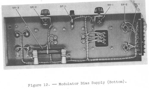
Modulator Bias Supply
- Restoration Photos
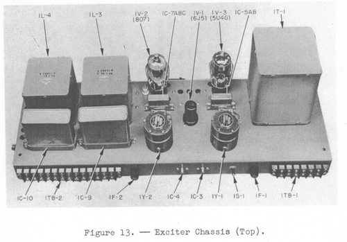
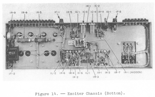
Exciter Chassis
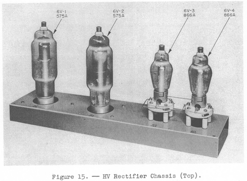
HV Rectifier Chassis
Modulator Power Supply
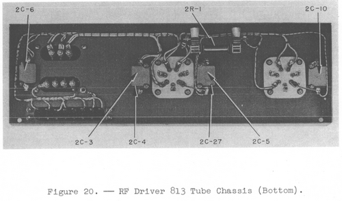
RF Driver 813 Tube Chassis
Pre-restoration Photos
