Difference between revisions of "AN~PRC-128"
RadioNerds (talk | contribs) (→Images) |
RadioNerds (talk | contribs) |
||
| (3 intermediate revisions by the same user not shown) | |||
| Line 5: | Line 5: | ||
*AN/PRC-128 handheld radio (PRC). | *AN/PRC-128 handheld radio (PRC). | ||
The items repairable at depot level are the power supply/audio (PS/A) assembly of the VA, the complete PA (including alternate module) and the RT portion of the PRC/128 (including alternate module). | The items repairable at depot level are the power supply/audio (PS/A) assembly of the VA, the complete PA (including alternate module) and the RT portion of the PRC/128 (including alternate module). | ||
| + | |||
| + | |||
| + | [[File:PRC-128-6.png|400px]] | ||
| + | |||
;The AN/PRC-128 radio system (PRC) consists of the following | ;The AN/PRC-128 radio system (PRC) consists of the following | ||
| Line 15: | Line 19: | ||
*Two rechargeable nickel-cadmium (NICAD) batteries. | *Two rechargeable nickel-cadmium (NICAD) batteries. | ||
The PRC is a two-band handheld receiver-transmitter. The PRC provides short range, ground-to-ground voice communications in the low VHF-FM (30 to 88 MHz) and high VHF-FM (130 to 174 MHz) bands. | The PRC is a two-band handheld receiver-transmitter. The PRC provides short range, ground-to-ground voice communications in the low VHF-FM (30 to 88 MHz) and high VHF-FM (130 to 174 MHz) bands. | ||
| + | |||
| + | |||
| + | [[File:PRC-128-5.png|400px]] | ||
| + | |||
;10-channel Operator Programmable-frequencv Capability | ;10-channel Operator Programmable-frequencv Capability | ||
| Line 32: | Line 40: | ||
:The PRC can transmit and receive utilizing a separate frequency for each channel programmed in the half-duplex mode. | :The PRC can transmit and receive utilizing a separate frequency for each channel programmed in the half-duplex mode. | ||
| + | |||
| + | |||
| + | [[File:PRC-128-4.png|400px]] | ||
==Technical Specifications== | ==Technical Specifications== | ||
| Line 136: | Line 147: | ||
:Distortion @ 2.0 Watts | :Distortion @ 2.0 Watts | ||
::10.0 % maximum | ::10.0 % maximum | ||
| + | |||
| + | |||
| + | |||
| + | ==Programming Frequencies== | ||
| + | |||
| + | ===Simplex=== | ||
| + | |||
| + | # Set the CHAN switch to the channel number to be reprogrammed | ||
| + | # Turn the radio off for a few seconds then back on | ||
| + | # Press SET within 10 seconds of turning the radio on, the Radio will be in programming mode, if one digit is shown in the display | ||
| + | # Press the INCR button until the LCD shows the desired digit | ||
| + | # Press the SET button. The next digit is displayed | ||
| + | # Repeat the above SET & INCR sequence until the complete frequency is displayed on the LCD | ||
| + | # Press the SET button to store the channel, LOAd will be displayed indicating that the channel frequency assignment has been stored. | ||
| + | # Change the CHAN button within 10 seconds to program a new frequency | ||
| + | |||
| + | |||
| + | {{message|Channel Steps|The last two digits can only be 00, 12, 25, 38, 50, 62, 75 or 88, due to the channel step of 12.5 kHz}} | ||
| + | |||
| + | |||
| + | |||
| + | ===Duplex=== | ||
| + | |||
| + | The Radio can use a split transmit and receive frequencies, usually used in repeater operation. The process is the same as with simplex except for a single step | ||
| + | |||
| + | |||
| + | ====Program the Receive Frequency==== | ||
| + | # Set the CHAN switch to the channel number to be reprogrammed | ||
| + | # Turn the radio off for a few seconds then back on | ||
| + | # Press SET within 10 seconds of turning the radio on, the Radio will be in programming mode, if one digit is shown in the display | ||
| + | # Press the INCR button until the LCD shows the desired digit | ||
| + | # Press the SET button. The next digit is displayed | ||
| + | # Repeat the above SET & INCR sequence until the complete frequency is displayed on the LCD | ||
| + | # Press and hold the PTT button, then press the SET button to store the channel, LOAd will be displayed indicating that the channel frequency assignment has been stored. The Transmit frequency is ready for programming. | ||
==Images== | ==Images== | ||
| Line 143: | Line 188: | ||
File:PRC-128-3.JPG | File:PRC-128-3.JPG | ||
</gallery> | </gallery> | ||
| − | |||
| − | |||
| − | |||
| − | |||
| − | |||
| − | |||
| − | |||
| − | |||
==Reference Files== | ==Reference Files== | ||
Latest revision as of 13:13, 26 November 2013
Contents
Overview
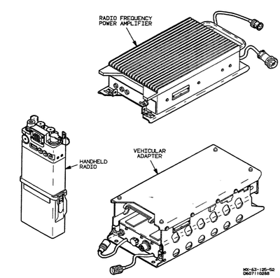
The Scope Shield Radio System consists of the following;
- Adapter Group OF-185/PRC (VA)
- Radio frequency power amplifier (PA)
- AN/PRC-128 handheld radio (PRC).
The items repairable at depot level are the power supply/audio (PS/A) assembly of the VA, the complete PA (including alternate module) and the RT portion of the PRC/128 (including alternate module).
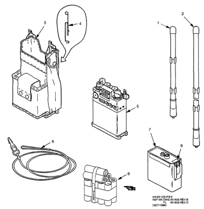
- The AN/PRC-128 radio system (PRC) consists of the following
- A receiver/transmitter (RT),
- Low band long range (LBLR) antenna;
- Low band short range/high band (LBSR/HB) antenna;
- Low band (30 to 88 MHz) and high band (130 to 174 MHz) RF/IF modules (one installed, other is alternate);
- Carrying pouch;
- Lanyard
- Two rechargeable nickel-cadmium (NICAD) batteries.
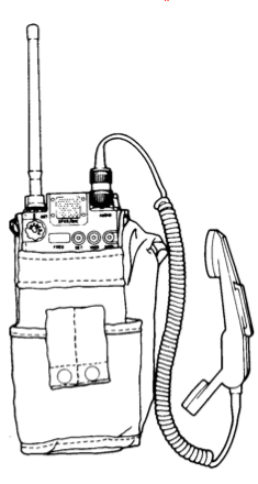
The PRC is a two-band handheld receiver-transmitter. The PRC provides short range, ground-to-ground voice communications in the low VHF-FM (30 to 88 MHz) and high VHF-FM (130 to 174 MHz) bands.
- 10-channel Operator Programmable-frequencv Capability
- The RT stores up to ten programmed channels (12.5 kHz increments) anywhere in the operating frequency range. A programmed RT can program another radio with channel/frequency information via a frequency transfer cable.
- Antenna Matching Switch
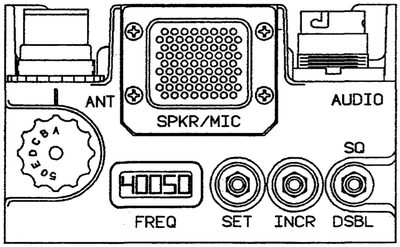
- The thumbwheel switch selects the proper antenna matching network for the transmit frequency. The "50" position provides a direct 50
ohm interface for test use. The "50" position is used for 130 to 174 MHz operation or with any 50 ohm external antenna. An antenna warning tone is activated if the switch position is incorrect with respect to the operating frequency.
- Warning Tones.
- The RT generates two separate warning tones; a low battery tone and an antenna mismatch tone.
- Liquid Crystal Display.
- A five-digit display indicates frequency, operational mode, and programming information to the operator.
- Half-duplex operation.
- The PRC can transmit and receive utilizing a separate frequency for each channel programmed in the half-duplex mode.
Technical Specifications
RT GENERAL CHARACTERISTICS
- Frequency ranges
- 30.0000 to 87.9875 MHz and 130.0000 to 173.9875 MHz
- Minimum channel spacing
- 25 kHz (+/- 25 kHz spacing to operate; can program in 12.5 kHz increments)
- Available channels
- 4640 (30-88 MHz band), 3520 (130-174 MHz band)
- Preset channels
- 10 (stored in non-volatile memory)
- Operating modes
- Clear Voice (Simplex and Half Duplex) FM
- Operating voltage
- 11 to 16 Vdc, 400 mAdc maximum.
- Low battery warning tone
- Four 400 Hz beeps at six second intervals when battery voltage drops below preset level
- Antenna mismatch tone
- 1000 Hz tone at 2 second intervals if selected operating frequency and ANT match switch position do not agree
RT RECEIVER CHARACTERISTICS
- Sensitivity
- 0.5 microvolts for 12 dB SINAD*
- Selectivity (+/- 25 kHz)
- -50 dB for 30-88 MHz, -60 dB for 130-174 MHz
- Squelch sensitivity
- 0.5 microvolts (maximum), noise operated
- Spurious response
- -60 dB
- IF rejection
- -60 dB
- Audio output
- Power
- 100 mW (nominal) into 47 ohms
- Distortion (@ 100 mW)
- 10% (maximum)
- Frequency response
- 300 to 3000 Hz (+1, -6 dB)
- Hum and noise
- Unsquelched
- 30dB below rated audio out
- Squelched
- 50 dB below rated audio out
- SINAD = Signal + Noise + Distortion Noise + Distortion
RT TRANSMITTER CHARACTERISTICS
- Power output
- 1.0 watt (minimum into 50 ohms)
- Spurious harmonic attenuation
- 43 dB below carrier (min.)
- Frequency stability
- 5 ppm (maximum) of operating frequency
- Audio
- Frequency response
- 300 to 3000 Hz (+1, -4 dB)
- Harmonic distortion
- 10% (maximum)
- Modulation
- +/-3 kHz, limited at 5 kHz (130-174 MHz)
- +/-4.5 kHz limited at 7.5 kHz (30-88 Mhz)
- FM hum and noise
- 30 dB below nominal deviation level (Low Band only)
- Squelch tone
- 150 +/- 2Hz'
PA CHARACTERISTICS
- Frequency ranges
- 30.0000 to 87.9875 MHz and 130.0000 to 173.9875 MHz
- Input power
- 25 - 28 Vdc, 3.0 Adc maximum
- RF Power Output (50 ohm load)
- BYPASS mode;
- 1 watt (ref. rf input)
- AMPL mode;
- 10 watts minimum, 20 watts maximum (internal adjust)
- Spurious harmonic attenuation
- 60 dB below carrier (minimum)
- Reference rf input level
- 0.25 watts minimum from RT
- RCV mode signal loss
- 1.0 dB max
PS/A CHARACTERISTICS
- Input power
- 10 to 32 Vdc; 150 watts max.
- Output power
- 14.5 to 15.5 Vdc @ .5 Adc max (RT).
- 26.0 to 27.0 Vdc @ 3.0 Adc max (PA).
- Charger current
- Nominal
- 30 mA
- Short-circuit
- 90 mA
- RCV Audio Output
- Power
- 2.0 watts nominal into 8 ohms
- Distortion @ 2.0 Watts
- 10.0 % maximum
Programming Frequencies
Simplex
- Set the CHAN switch to the channel number to be reprogrammed
- Turn the radio off for a few seconds then back on
- Press SET within 10 seconds of turning the radio on, the Radio will be in programming mode, if one digit is shown in the display
- Press the INCR button until the LCD shows the desired digit
- Press the SET button. The next digit is displayed
- Repeat the above SET & INCR sequence until the complete frequency is displayed on the LCD
- Press the SET button to store the channel, LOAd will be displayed indicating that the channel frequency assignment has been stored.
- Change the CHAN button within 10 seconds to program a new frequency
Duplex
The Radio can use a split transmit and receive frequencies, usually used in repeater operation. The process is the same as with simplex except for a single step
Program the Receive Frequency
- Set the CHAN switch to the channel number to be reprogrammed
- Turn the radio off for a few seconds then back on
- Press SET within 10 seconds of turning the radio on, the Radio will be in programming mode, if one digit is shown in the display
- Press the INCR button until the LCD shows the desired digit
- Press the SET button. The next digit is displayed
- Repeat the above SET & INCR sequence until the complete frequency is displayed on the LCD
- Press and hold the PTT button, then press the SET button to store the channel, LOAd will be displayed indicating that the channel frequency assignment has been stored. The Transmit frequency is ready for programming.
Images
Reference Files
- MAINTENANCE INSTRUCTIONS WITH ILLUSTRATED PARTS BREAKDOWN
- RADIO SET
- AN/PRC-128 (PN 901608-801)
- RP [sic] POWER AMPLIFIER (PN901603-801)
- ADAPTER GROUP
- OF-185/PRC (901602-801)
- 18 November 1999


