Difference between revisions of "AN~CRN-2"
Jump to navigation
Jump to search
RadioNerds (talk | contribs) |
(→Images) |
||
| (One intermediate revision by one other user not shown) | |||
| Line 8: | Line 8: | ||
# Rectifier Power Supply | # Rectifier Power Supply | ||
| + | |||
| + | ==Images== | ||
| + | [[File:AN_CRN-2_Data.png|400px]] | ||
| + | [[File:AN.CRN 2.01.jpg|400px]] | ||
| + | [[File:AN.CRN 2.02.jpg|400px]] | ||
==Technical Details== | ==Technical Details== | ||
Latest revision as of 16:57, 4 March 2017
Contents
Overview
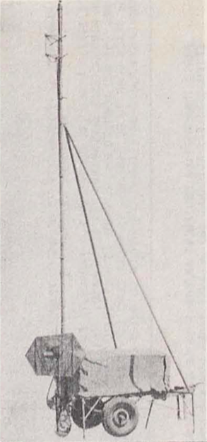
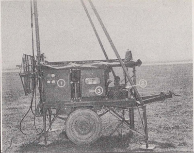
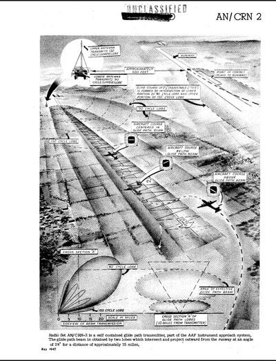
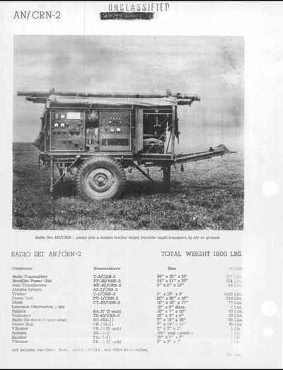
Is a glide path transmitter which gives the angle of approach. This is indicated on a horizontal pointer contained in the AN/ARN-4, instrument landing receiving equipment.
- Transmitter and Modulator
- Gasoline Engine Power Supply
- Rectifier Power Supply
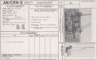
Images
Technical Details
- Frequency Range
- 330 - 340 mHz
- Number of Crystals
- 1
- Preset Frequencies
- 335
- Antenna
- Folded Dipoles
- Tuning
- Xtal Controlled
- Power Source
- PE-141 Motor Generator (115v 60 Cycles)
- Power Output
- 25 Watts of CW Power
- Type of Signal
- Straight line glide path - Double Bean MCW system
- Range
- 15 Miles at 3000 Ft.
Tubes
- 1 - 6JS
- 2 - 6SJ7
- 1 - 6SK7
- 3 - 5V4G
- 3 - 6SN7GT
- 1 - 9002
- 1 - 829B
- 1 - 832
- 2 - 836
- 4 - 8025
- 1 - VR90
- 1 - VR150
