Difference between revisions of "SCR-242"
| Line 20: | Line 20: | ||
* [[I-65]] indicator | * [[I-65]] indicator | ||
* [[TM-180]] J-box | * [[TM-180]] J-box | ||
| + | * [[DM-20]] | ||
==Reference Files== | ==Reference Files== | ||
Revision as of 09:36, 24 June 2020
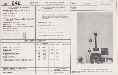
Radio. Compass SCR-242-B was designed primarily for use In U. S. Army aircraft. This equipment is a 12 tube superheterodyne, with an intermediate frequency amplifier at 112.5 Kc. The equipment is capable of being locally or remotely controlled at the option of the local operator. The frequency range of the equipment is from 150 to 1500 Kc., which is covered in three bands calibrated in kilocycles, as follows:
- Band 1: 150 to 325 Kc.,
- Band 2: 325 to 695 Kc.,
- Band 3: 695 to 1500 Kc.
Only the frequency band in use is visible. This equipment is manually tuned from either control posltion and the bands are switched electrically from the position having control. When used in conjunction wIth a suitable non-directional antenna, one or two headsets, ~ 12 to 14 volt direct current power supply and necessary interconnecting wiring, this radio compass is a complete operable unit capable of providing:
- VIsual, unidlrectional, right-left indication of the arrival of radio frequency energy with respect to the plane of the loop and simultaneous "On Course" aural reception of modulated radio frequency energy.
- Aural reception of modulated radio frequency energy using a non- dlrectional antenna.
- Aural reception of modulated radio frequency energy using a loop antenna, especially during periods of rain and snow static.
- Aural-null directionl indications of the arrival of modulated radio loop antenna, especially during periods of rain and snow static. A fixed loop mounting is supplied for visual or aural-null "homing." A rotable loop mounting is supplied for visual or aural-null homing and direction finding and for anti-rain or snow static reception. Ice removers are supplied.for use in loops exposed to icing conditions.
Components
- BC-310 Rec. FT-145, DM-18
- BC-311 Cbx.
- LP-13 ant.
- M-169 mounting cap
- I-65 indicator
- TM-180 J-box
- DM-20
Reference Files
- TO 08-10-11 , 21, 27
 Instruction book for radio compass SCR-242-A[1]
- Radio Compass SCR-242-A
- 19 March 1937
 Instruction book for radio compass SCR-242-B[2]
- Radio Compass SCR-242-B
- 23 Oct. 1937
References
- ↑ Instruction book for radio compass SCR-242-A,
- "US Army Technical Manual Collection,"
- from the CECOM Historical Office archive, Aberdeen Proving Ground, MD.
- CECOM Historical Office
- "US Army Technical Manual Collection,"
- ↑ Instruction book for radio compass SCR-242-B,
- "US Army Technical Manual Collection,"
- from the CECOM Historical Office archive, Aberdeen Proving Ground, MD.
- CECOM Historical Office
- "US Army Technical Manual Collection,"
