Difference between revisions of "AN~PPS-6"
Jump to navigation
Jump to search
RadioNerds (talk | contribs) |
RadioNerds (talk | contribs) |
||
| Line 5: | Line 5: | ||
==Operating Instructions== | ==Operating Instructions== | ||
These operating instructions are found printed on the data plate attached to the unit. | These operating instructions are found printed on the data plate attached to the unit. | ||
| − | |||
| − | |||
| − | |||
| − | |||
| − | |||
| − | |||
===Starting the Equipment=== | ===Starting the Equipment=== | ||
| Line 31: | Line 25: | ||
===Stopping the Equipment=== | ===Stopping the Equipment=== | ||
# Place <u>Power</u> switch <u>(OFF-STBY-XMIT)</u> at <u>OFF</u> position. | # Place <u>Power</u> switch <u>(OFF-STBY-XMIT)</u> at <u>OFF</u> position. | ||
| − | |||
| − | |||
==Reference Files== | ==Reference Files== | ||
Revision as of 14:10, 17 March 2014
Contents
Operating Instructions
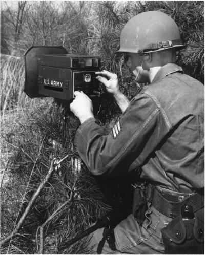
These operating instructions are found printed on the data plate attached to the unit.
Starting the Equipment
- Set meter switch to BAT position and check battery condition on Test Meter
- Set Power switch (OFF-STBY-XMIT) at XMT position.
- Set Area Search switch (MODE 1-2-3) at MODE 3
- Set Adjust Range Control knob to estimated center (in meters) of desired target area
- Set Meter switch to AGC/EL position
- Sight on desired sector, using front and rear sights
- Adjust Sensitivity control so that Test Meter points to AGC line.
- Loosen Elevation knob and adjust radar for maximum AGC deflection on Test Meter while adjusting Sensitivity control to maintain meter pointer near AGC line.
- Set Area Search switch (Mode 1-2-3) to Mode 1 or 2 as desired, and Auto-Man clutch to Man position.
- On Angular control, adjust sector scan ring to center of desired scanning sector.
- Manually scan desired sector by moving receiver transmitter unit to azimuth. With radar trained on spot giving lowest reading, adjust Sensitivity control so that Test Meter pointer is on AGC line. Lock Sensitivity control.
- Again, Manually scan desired sector and set Volume control for satisfactory max noise level in headset.
- Set Auto-Man clutch to Auto position and monitor headset for moving target in area under surveillance.
Stopping the Equipment
- Place Power switch (OFF-STBY-XMIT) at OFF position.
Reference Files
![]() USAELRDL Technical Report 2421
USAELRDL Technical Report 2421
- Assembly Design of Miniature Lightweight Handheld Radar Set AN/PPS-6
- HARRY H. FRENCH
- UNITED STATES ARMY
- ELECTRONICS RESEARCH AND DEVELOPMENT LABORATORIES FORT MONMOUTH, N.J.
- SEPTEMBER 1963
![]() DESIGN PARAMETERS FOR A LIGHTWEIGHT HANDHELD RADAR SYSTEM AN/PPS-6( )
DESIGN PARAMETERS FOR A LIGHTWEIGHT HANDHELD RADAR SYSTEM AN/PPS-6( )
- Army Signal Research and Development Laboratory Fort Monmouth, New Jersey
- Dunlap and Associates, Inc. 429 Atlantic Street Stamford, Connecticut
- Leroy L. Vallerie
- Robert T. McCay
- Jack Wm. Dunlap, Program Director
- January 1962
