Difference between revisions of "SCR-277"
| Line 2: | Line 2: | ||
==Specifications== | ==Specifications== | ||
| − | The SCR-277 was used as a navigation aid. It included the [[BC-467]] radio transmitter with an radio frequency RF output power of 800 watts, the [[BC-468]] Goniometer, and [[BC-342]] radio receiver. Frequencies utilized were 200-400 KHz for transmission and 1.5-18 MHz for reception. Radio range homing equipment transmitted tone identification signals to aircraft that lacked a radio compass but were equipped with [[AN~ARC-5]] command sets. Range was approximately 300 miles. It was powered by a single [[PE-90]] generator. | + | The SCR-277, that was housed in the [[K-29 trailer]], was used as a navigation aid. It included the [[BC-467]] radio transmitter with an radio frequency RF output power of 800 watts, the [[BC-468]] Goniometer, and [[BC-342]] radio receiver. Frequencies utilized were 200-400 KHz for transmission and 1.5-18 MHz for reception. Radio range homing equipment transmitted tone identification signals to aircraft that lacked a radio compass but were equipped with [[AN~ARC-5]] command sets. Range was approximately 300 miles. It was powered by a single [[PE-90]] generator. |
==Use== | ==Use== | ||
Revision as of 13:50, 18 April 2016
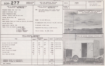
The SCR-277 was a mobile, trailer mounted radio range for radio guidance of aircraft. It was standardized by the U.S. Army in June 1941.
Specifications
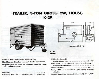
The SCR-277, that was housed in the K-29 trailer, was used as a navigation aid. It included the BC-467 radio transmitter with an radio frequency RF output power of 800 watts, the BC-468 Goniometer, and BC-342 radio receiver. Frequencies utilized were 200-400 KHz for transmission and 1.5-18 MHz for reception. Radio range homing equipment transmitted tone identification signals to aircraft that lacked a radio compass but were equipped with AN~ARC-5 command sets. Range was approximately 300 miles. It was powered by a single PE-90 generator.
Use
In operation the transmitter sends out signals coded "A" or "N" in each of the four quadrants around the beacon. The signals overlap on the range, providing the pilot of the aircraft an indication of his position in relation to location of the beacon. Thus, if he is heading toward the beacon he will receive an aural signal coded "A" or "N" if he is between the beam, and when he is on the beam he will receive "AN" signal. Over land areas the beacon has a range of about 300 miles, while over water areas the range is extended to about 1,000 miles. Charts prepared for air navigation show the position and the orientation of the various beacons.
References
- TM 9-2800 Standard Military Motor Vehicles. dated 1 September 1943
- TM 9-2800 Military vehicles dated October 1947
![]() TM 9-2800 1947 page 201
TM 9-2800 1947 page 201
- TM 11-227 Signal Communication Directory. dated 10 April 1944
- TM 11-487 Electrical Communication systems Equipment. dated 2 October 1944
- Graphic Survey of Radio and Radar Equipment Used by the Army Airforce. section 3 Radio Navigation Equipment Dated May 1945

