Difference between revisions of "SCR-609"
| Line 81: | Line 81: | ||
* '''TM 11-2714''', 44. Installation of Radio Equipment in Carrier, Personnel, Half-Track, M3, 40 pages. PB 23462 - BSIR 2(2):87; 07/05/46 {{pdf|TM 11-2714 1944.pdf|TM 11-2714 1944}} (Museum TD, Soesterberg NL/Corjan de Wit} | * '''TM 11-2714''', 44. Installation of Radio Equipment in Carrier, Personnel, Half-Track, M3, 40 pages. PB 23462 - BSIR 2(2):87; 07/05/46 {{pdf|TM 11-2714 1944.pdf|TM 11-2714 1944}} (Museum TD, Soesterberg NL/Corjan de Wit} | ||
| + | |||
| + | * '''TM 11-2717''', 44. Installation of Radio and Interphone Equipment in Car, Scout, M3A1, 68 pages. PB 23464 - BSIR 2(4):251; 07/26/46 {{pdf|TM 11-2717 1944.pdf|TM 11-2717 1944}} (Museum TD, Soesterberg NL/Corjan de Wit}} | ||
* FM 6-150 organic field artillery air observation. (page 69 outlines installation in spotter aircraft) | * FM 6-150 organic field artillery air observation. (page 69 outlines installation in spotter aircraft) | ||
Revision as of 02:41, 30 March 2019
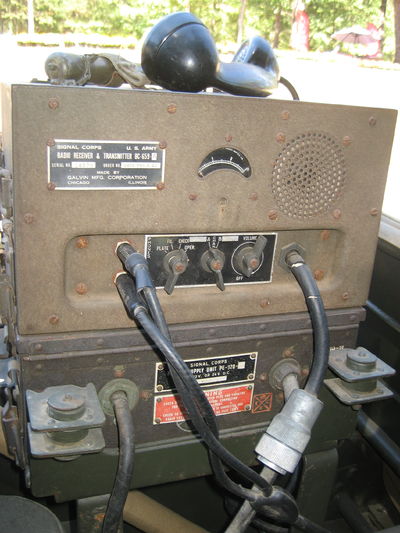
Radio Set SCR-609 is a portable set capable of being carried in any vehicle of the Field Artillery. (including aircraft like the L-4) Radio Sets SCR-609 and SCR-610 and are the same except for supply. Radio Set SCR-609 uses batteries. Radio set SCR-610 is equipped with a power supply to operate from vehicular battery as well as self-contained battery supply in case CS-79.
Specifications
- Frequency Range
- 27.0 - 38.9 mHz
- Number Of Crystals
- 120
- Preset Frequencies
- 2
- Antenna
- Fishpole Type AN-29-C
- W-29. W-128
- Tuning
- Crystal
- Power Source
- Dry Batteries BA-39, 40, 41
- Power Output
- 2 Watts
- Modulation Type
- FM
- Components
- SCR-609
- SCR-610
- Tubes
- 5 - 1LN5
- 2 - 1291
- 4 - 1299
- 1 - 1LH4
- 1 - 1294
- 1 - 1LC6
hack notes
The original battery cable for PE-97/117/120 is SIG STK NR 3E4300. LOA 9'-0". This is a four-conductor black rubber (later neoprene) jacketed 1/2" OD cable with two #14 AWG (red and green) and two #10 AWG (white and black) conductors. The red and white are tied together and the black and green are tied together at the battery or terminal box end. At the power supply end the conductors go to different locations.
This cord isn't made any more (even at the time it was probably custom made for the purpose). You can substitute #12-4 SJOOW which is black neoprene jacketed with an OD of 0.48". I would recommend cutting the wire to minimum required length for the installation rather than coiling up the excess. Especially in a 6-volt vehicle. The individual insulation colors should be the same as in the original and you should use the red and white for positive and the black and green for negative (ground).
The outer jack will probably have white printing on it which should be removable with acetone. also Current issue CX4721 and CX4720 work best.4 number 10 conductors.
Images
Reference Files
- Schematic Diagrams for Maintenance of Ground Radio Communication Set
- October 1942
- TM 11-4023
- Radio Receiver and Transmitters
- BC-659-A, -B, -H, and -J,
- Repair Instructions. War Dept.
- Jun. 1945. 56 p.
- WAR DEPARTMENT TECHNICAL MANUAL OF RADIO SETS SCR-609A AND -B AND SCR-610A AND -B OF APRIL 1945
- TM 11-615 1-Aug-42
- TM 11-2714, 44. Installation of Radio Equipment in Carrier, Personnel, Half-Track, M3, 40 pages. PB 23462 - BSIR 2(2):87; 07/05/46
![]() TM 11-2714 1944 (Museum TD, Soesterberg NL/Corjan de Wit}
TM 11-2714 1944 (Museum TD, Soesterberg NL/Corjan de Wit}
- TM 11-2717, 44. Installation of Radio and Interphone Equipment in Car, Scout, M3A1, 68 pages. PB 23464 - BSIR 2(4):251; 07/26/46
![]() TM 11-2717 1944 (Museum TD, Soesterberg NL/Corjan de Wit}}
TM 11-2717 1944 (Museum TD, Soesterberg NL/Corjan de Wit}}
- FM 6-150 organic field artillery air observation. (page 69 outlines installation in spotter aircraft)


