Difference between revisions of "AN~MRN-1"
Jump to navigation
Jump to search
RadioNerds (talk | contribs) |
RadioNerds (talk | contribs) |
||
| Line 24: | Line 24: | ||
;Type of Signal | ;Type of Signal | ||
:CW, MCW, Voice | :CW, MCW, Voice | ||
| + | |||
| + | |||
| + | ==Images== | ||
| + | [[File:AN_MRN-1_Data.png|400px]] | ||
| + | |||
Revision as of 00:23, 8 December 2013
Overview
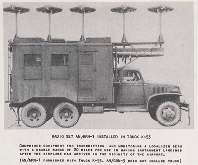
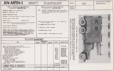
Transmits and monitors a localized beam for use in making instrument landing after aircraft has arrived in the vicinity of the airport.
Technical Details
- Frequency Range
- 108.3 - 110.3 mHz
- Number of Crystals
- One
- Antenna
- Five alford loops in same horizontal plane.
- Tuning
- XTAL
- Power Source
- 110 Volts, 60 Cycle AC Gasoline engine generator
- Power Output
- 25 Watts
- Range
- 40 Watts at 2500 ft.
- 70 Watts at 6000 ft.
- 100 Watts at 10,000 ft.
- Type of Signal
- CW, MCW, Voice
Images
Components
- Radio Transmitter Equipment RC-107
- Localizer Transmitter Equipment Consists of
- Control Box BC-915
- Radio Transmitter BC-751
- Modulator & Bridge BC-752
- Course Detector BC-753 (Fixed)
- Course Detector BC-754 (Portable)
- Field Intensity Meter BC-755
- Indicator BC-777 Alarm

