NVIS
Contents
Near-Vertical Incident Sky Wave Communications
The standard communications techniques used in the past will not support the widely deployed and fast moving formations of today’s Army. Coupling this with the problems that can be expected in deploying multi-channel LOS systems with relays to keep up with present and future operation, HF radio and the NVIS mode take on new importance. The HF radio is quickly deployable, securable, and capable of data transmission. HF (such as the AN/PRC-150 [C]) will be the first, and frequently the only, means of communicating with fast-moving or widely separated units. With this reliance on HF radio, communications planners, commanders, and operators must be familiar with NVIS techniques and their applications and shortcomings in order to provide more reliable communications.
NVIS propagation is simply sky wave propagation that uses antennas with high angle radiation and low operation frequencies. Just as the proper selection of antenna can increase the reliability of a long range circuit, the same holds true for short range communications.
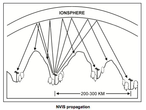
9-87. NVIS propagation uses high take-off angle (60–90 degrees) antennas to radiate the signal almost straight up. The signal is then reflected back from the ionosphere and returns to Earth in a circular pattern all around the transmitter. Because of near vertical radiation angle, there is no skip zone (skip zone is the area between the maximum ground wave distance and the shortest sky wave distances where no communications are possible). Communications are continuous out to several hundred kilometers from the transmitter. The nearly vertical angle of radiation also means lower frequencies must be used.
Generally, NVIS propagation uses frequencies up to 8 MHz. The steep up and down propagation of the signal gives the RTO the ability to communicate over nearby ridge lines, mountains, and dense vegetation. A valley location may give the RTO terrain shielding from hostile intercept or protect the circuit from ground wave and long wave interference. Antennas used for NVIS propagation need high take-off angle radiation with very little ground wave radiation. Refer to Figure 9-18 for an example of NVIS propagation.
Using the HF antenna table matrix in Appendix C, the AS-2259/GR and the half wave dipole are the only antennas listed that meet the requirements of NVIS propagation. While the inverted V and inverted L have high angle radiation, they can also have strong ground wave radiation that could interfere with the close-in NVIS communications.
Disadvantages of Using the NVIS Concept
It is also important to understand that where both NVIS and ground wave signals are present, the ground wave can cause destructive interference. Proper antenna selection will suppress ground wave radiation and minimize this effect while maximizing the amount of energy going into the NVIS mode.
Advantages of Using the NVIS Concept
- following are advantages of using NVIS in a tactical environment
- There are skip-zone-free omnidirectional communications.
- Terrain does not affect loss of signal. This gives a more constant received signal level over the operational range instead of one which varies widely with distance.
- Operators are able to operate from protected, dug-in positions. Thus tactical commanders do not have to control the high ground for HF communications purposes.
- Orientation, such as, doublets and inverted antennas are not as critical.
- following are advantages of using NVIS in an EW environment
- There is a lower probability of geolocation - NVIS energy is received from above at very steep angles, which makes direction finding (DF) from nearby (but beyond ground wave range) locations more difficult.
- Communications are harder to jam. - Ground wave jammers are subject to path loss. Terrain features can be used to attenuate a ground wave jammer without degrading the desired communication path. The jamming signal will be attenuated by terrain, while the sky wave NVIS path loss will be constant. This will force the jammer to move very close to the target or put out more power. Either tactic makes jamming more difficult.
- Operators can use low power successfully. - The NVIS mode can be used successfully with very low power HF sets. This will result in much lower probabilities of LPI/D.
Reference Files
- Near Vertical Incident Skywave Communications (NVIS)
- 2000
