Converting Dash Mount EF Johnson Challenger Radios to Remote Mount
The Ef johnson Challenger series radios are quite flexible for older technology. You can take a dash mount radio and convert it to remote mount if you have the remote head and junction box.
Contents
- 1 Challenger Remote Components
- 2 What you have to do to convert to remote mount
- 3 Choosing the Proper Radio
- 4 Remove the Power/volume control, Install the relay
- 5 Cable Connections
- 6 Programming the Channel Text into the Remote Head
- 7 Optional: Jumper out the ignition sense connection
- 8 Troubleshooting
Challenger Remote Components
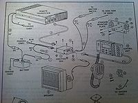
The radio is connected to the junction box via a n 8 pin modular connector then this junction box is connected to the remote head. Although the image is clearly of an 86xx series, the remote heads are the same
What you have to do to convert to remote mount
The process to convert a dash mount to remote mount is straight forward..
- Select the proper radio
- Acquire the parts needed
- Control Unit (Remote head) Part #250-8610-50x (often marked as 3047D042A on Ebay)
- Junction Box Part #023-8610-520
- 12V Relay (MZ-12HG-K-U)
- Network Patch Cable, flexible type
- Remove the current power / Volume control
- Install the relay
- Hook up the cable
- Program the remote head
Choosing the Proper Radio
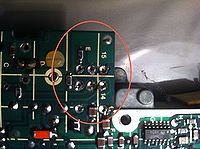
Not all challenger series radios have the necessary configuration or parts to convert to a remote. The main item to look for are the additional mounting holes for the relay and the presence of other parts on the bottom of the board.
Remove the Power/volume control, Install the relay
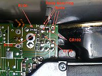
carefully unsolder the existing power / volume control. This is easier if you remove the triangular (well sort of) metal plate on the bottom of the radio.
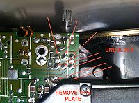 Solder points for the power switch
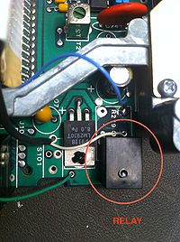
Install the relay. Note that the relay is on the most forward holes, not the same as the switch just removed.
Cable Connections
The connection cable between the radio and the remote junction box is an 8 pin modular plug, much like an RJ45. The standard RJ45 (network cable) wont fit directly, but you can file down each side a bit and it will work fine. I usually take a 'flexible' 8 ft network patch cable and cut one connector off, then hard wire this cable into the radio. Although the factory has a modular plug installed at the radio, they just really add an additional failure point.
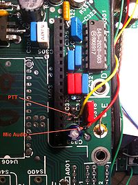
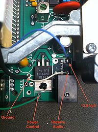
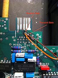
The colors in the table correspond to the images below. In EF Johnson service manuals they refer to the connections as A123456B, however they are just pins 1-8 for the plug. I have included the EF Johnson designation in parenthesis. 'See Junction Box Details below for pinout'
- Cable Connections
- 1 - (A) Orange - Receive Data
- 2 - (1) Ground Braid
- 3 - (2) Red - Mic audio
- 4 - (3) Green - Power Control
- 5 - (4) Yellow - PTT
- 6 - (5) Blue - 13.4 volt source
- 7 - (6) White - Receive Audio
- 8 - (B) Brown - Transmit Data
The Connections
[OK No comments about my soldering :-), I'm actually quite good at it, but this board was used and has been installed and uninstalled in several radios it seems]
The ground braid is shown connected to an unused channel down control, since the dash mount radio would have the connector there, you can either remove it or find another ground.
Programming the Channel Text into the Remote Head
To define the text into the remote head, you will need to use the RPTCLU.EXE programming application. Although some of the RP7175.exe ones have a space for the text, i have never gotten them to work properly.
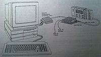
you will need to use the additional adaptor and the modular cable to program the head and radio. The picture above shows the configuration. you will disconnect the junction box from the radion and depending on what you are programming, the programming cable is plugged into the radio side or the remote side. Once the cable is plugged in to the head and powered on, you will see a message 'programming mode'. The radio doesnt really have an visual indicators, but if the numeric display is there, you will see 'Pr' on it.
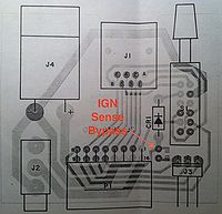
Optional: Jumper out the ignition sense connection
the remote head has a facility to have remote ignition sense. Where the radio will shut off after a programmed set of time if 12v is removed from this pin. if you want to disable this you need to install a jumper of solder across the pad.
Troubleshooting
Loud Buzz from the Relay when head is powered on
The ground connection wire between the radio and the head is severed, this causes the relay to oscillate.
Powering on the head shows no text, but does light up
the red programming switch on the junction box is in the wrong position
Unable to put the head in programming mode
the red programming switch on the junction box is in the wrong position
