AN/GSA-7
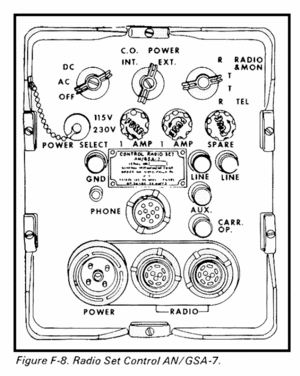
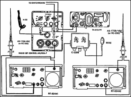
Radio Set Control AN/GSA-7 is a small light- weight electronic switching device for use in in- tegrated wire-radio systems. It is also used to interconnect radio transceivers, or transmitters and receivers, with local battery telephone equip- ment on a push-to-talk basis. After the radio set control is connected and power is applied to it and to the radio, no attendant is necessary. The associated radio transmitter is turned on and off automatically by the wire equipment user. The radio set control can be used in wire-to-wire (via radio), wire-to-radio, or radio-to-wire communication. Two radio set controls can also be used to interconnect two push-to-talk radio sets for retransmission (automatic relay) purposes. The radio set control also provides facilities for an operator (monitor) to either listen or talk to both ends of a circuit or to signal in either direction. The equipment is operable on the ground, or in a stationary vehicle.
System Application
a. Two radio set. controls can be used to interconnect two local battery telephone equipments via radio as illustrated in A, figure 2. Switchboards SB-22/PT and SB-18/PT can be used for this application.
b. The radio set control can be used to interconnect a remote radio location, either fixed or moving, wit h local battery telephone equipment as illustrated in B, figure 2. On a call from the telephone equipment to the remote radio, the remote radio operator will hear a burst of 1,600- cycle-per-second (cps) tone from his receiver in response to the telephone equipment user’s 20-cps ringing signal. For the radio equipment user to call the telephone equipment of the radio set control, the radio station transmitter must emit a burst of 1,600-cps tone. When using radio transmitters in the Radio Transmitter RT-66/GRC, RT-67/GRC, and RT-68/GRC series, this can be accomplished by momentarily holding the transmitter DIAL LIGHT-RING switch in the RING position.
c. Two radio set controls may be used for retransmission purposes as illustrated in C, figure 2. Each radio receiver must have either a carrier-operated relay or direct current (dc) volt age output when receiving a radio frequency (RF) carrier to enable the radio set control to retransmit messages from the receiver of one radio set to the transmitter of the other radio set.
Technical Characteristics
- Power supply
- Self-contained, with choice of operation from: 22-30 volts dc; 115 volts +10%, or 230 volts ±10%, 50 to 400 cps ac. Approximate power drain is 25 watts.
- Maximum wire distance.
- 10 miles.
- Maximum radio distance.
- Depends upon radio sets used.
- Means of ringing via radio
- Ringing frequencies.
- 15 to 25 cps (wire) converted to 1,000 cps (radio) ; 1,600 cps (radio) converted to 20 cps (wire).
- 1,600-cps sensitivity
- 20 dbm of 1,600 ±30 cps into 600 ohms at the radio receiver audio terminals.
- 20-cps sensitivity
- 20 volts rms applied to LINE terminals.
- 1,600-cps output level.
- Between -6 and -11 dbm into 150 ohms at 1,600 cps at the radio transmitter audio terminals.
- 20-cps output level
- 40 volts rms minimum at telephone line terminals.
- Means of obtaining speech immunity in 1,600- cycle receiving circuit.
- Combination of selectivity, delay, and limiter.
Additional Files
- Radio Set Control AN/GSA-7
- May 1958
- ORGANIZATIONAL, DIRECT SUPPORT, AND GENERAL SUPPORT MAINTENANCE
- REPAIR PARTS AND SPECIAL TOOLS LISTS
- DEPOT MAINTENANCE REPAIR PARTS AND SPECIAL TOOLS)
- RADIO SET CONTROL
- AN/GSA-7 (NSN 5820-00-543-1397)
- September 1976
- Radio Wire Integration
- Installation and Operation Tips
- Users Guide
- 30 November 1976

