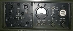
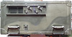
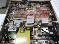
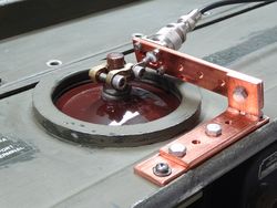
AN/TRC-75
Jump to navigation
Jump to search
radio transceiver
components:
R-761/ARC-58 transceiver
T-730/TRC-75 linear power amplifier
C3141/TRC-75 control box
C-2848/TRC-75 antenna coupler control
CU-749/TRC-75 antenna coupler
AM-2360/TRC-75 microphone and audio aplifier
CV-786/TRC-75 RTTY modem
RF-111/TRC-75
All the above components are inclosed in the case CY 2600/TRC-75.
The power for the TRC-75 is from the inverter PP-2352/UR.
wich convert the vehicular 28 Vdc to a three phases 115 Vac 400Hz ,
one phase is filtered for use with the receiver R-761/ARC-58 and for the various servo amplifiers used in the apparatus.
Technical Details
| General | Characteristics |
|---|---|
| Frequency range | 2000 - 29999 KHz |
| Frequency steps | 1 KHz |
| Frequency stability | 0.5 ppm |
| Tuning | automatic, servocontrolled |
| Modulation modes | AM , USB, LSB, CW, FSK |
| Antenna | Whip 15 -30 feet, Long wire 45 - 95 feet, dipole 50 Ohm |
| Working temperature | +50°C -40°C |
| vacuum tubes used | 40 |
| Transistors used | 114 |
| Power | 115 Vac (phase neutral) 400Hz 3 phases 2.500 W max |
| Dimensions | W 48.5' (123 cm), H 20' (51 cm), D 30,5' (77 cm) |
| Weight | 325 pounds, 147 kg |
| Receiving | Characteristics |
|---|---|
| Sensitivity | better than 1 microVolt SSB, 3 microvolt AM for 10db S+N/N |
| Selectivity | 2.6 KHz a 3db LSB USB e 6 KHz in AM |
| Audio output | 1.5 W |
| output impedance | 600 Ohm in loudspeaker |
| Transmitting | Characteristics |
|---|---|
| SSB | 900W PEP high power, 400 W PEP low power |
| AM | 180 W carrier high power, 80 W low power |
| CW RTTY | 700 W high power, 100 W low power |
| Third order intermodulation | -30db |
| Duty cycle | SSB and FSK continuous, AM 50% |


