Difference between revisions of "AS-1729~VRC"
RadioNerds (talk | contribs) |
RadioNerds (talk | contribs) |
||
| Line 79: | Line 79: | ||
| − | == | + | ==Reference Files== |
;{{pdf|TM_11-5985-262-14.pdf|TM 11-5985-262-14}} | ;{{pdf|TM_11-5985-262-14.pdf|TM 11-5985-262-14}} | ||
:OPERATOR’S, ORGANIZATIONAL, DIRECT SUPPORT, AND GENERAL SUPPORT MAINTENANCE MANUAL | :OPERATOR’S, ORGANIZATIONAL, DIRECT SUPPORT, AND GENERAL SUPPORT MAINTENANCE MANUAL | ||
Revision as of 15:33, 4 August 2013
The AS-1729/VRC Vehicular Antenna is a center-fed whip antenna that operates in the frequency range of 30-76 MHz. The primary application and use of this antenna is to replace the Antenna AT-912/VRC and operate as a vehicular antenna in the following radio sets: AN/VRC-12 through AN/VRC-49, AN/VRC-53, AN/VRC 64, AN/VRC- 65, AN/VRC-6550, and AN/GRC-160, as well as many other VHF Radio Sets that require vehicular installation.
In addition the AS-1729/VRC Antenna can be used to extend the communication range in radio sets: An/PRC-25, AN/PRC-77, and AN/PRC-1177, as well as many other UHF radio sets operating in the 30-76 MHz frequency range.
The AS-1729/VRC is an omnidirectional antenna assembly built to MIL-A-55288C (CR) specifications. The antenna is vertically polarized and centerfed, operating in the 30-76 MHz range, with 10 frequency band segments. Band switching is automatic if the antenna is connected to a compatible transceiver with automatic antenna switching capabilities. The band switching may be exercised manually by operating the control located at the base of the matching unit if the antenna is connected to other receivers and transceivers.
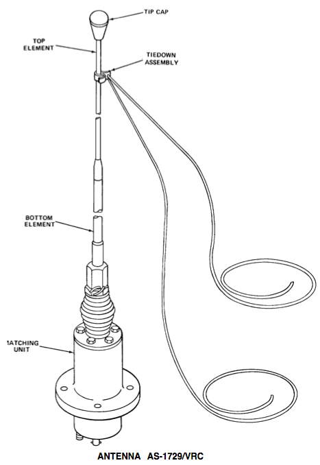
The AS-1729/VRC consists of three units: MX-6707 Base Matching unit with spring and cable assembly; AS-1730 Lower Antenna element; and AT-1095 Upper element. The based matching unit is interfaced to the vehicle with four bolts and a gasket provided with the hardware kit. Electrical connections consist of an RF input connector for connection to the RF outputs on the transmitter/transceiver; automatic band switching control for connection to transmitters/transceivers with automatic band switching characteristics; and a ground stud which electrically grounds the base matching unit to the vehicle.
The AS-1730 lower antenna element and AT-1095 upper antenna element are fastened together by tapered lock ferrules, and then installed on top of the base matching unit providing a complete 30-76 MHz antenna system.
The AS-1729/VRC is designed for use on the outside of jeeps, tanks, armored-personnel carriers, weapons carriers, or crew served weapons.
- FEATURES OF THE AS-1729/VRC
- Wide coverage
- Operates over 30 to 76 MHz range in 10 band segments
- Automatic Tuning
- Any one of 10 segments automatically selected by a solenoid-driven switch in the matching unit; solenoid is controlled from receiver-transmitter RT-246/VRC or RT-524/VRC, or from amplifier power supply OA-3633/GRC.
- Manual Override
- Band segments can be manually selected on the antenna base assembly.
- Reliable
- Operates under extreme environmental conditions; meets U.S. military specifications; assures trouble-free communication under severe combat conditions; flexible base spring permits bending and prevents breakage (tie-down kit allows antenna to be bent and tied to vehicle).
Contents
SPECIFICATIONS
- Frequency Range
- 30-76 MHz.
- Band Segments
- 10.
- Tuning
- Automatic & manual.
- Solenoid Operating Voltage
- 24 Vdc nominal.
- Input Impedance
- 50 ohms.
- VSWR
- 3 : 1 maximum.
- Power Handling
- 70 W maximum.
- Operating Temperature Range
- -40°C to +65°C, -40°F to +150°F.
- Overall Length
- 0-1/2 feet (3-1/4 meters).
- Components
- Antenna Element AT-1095/VRC (upper section).
- Antenna Element AS-1730/VRC (lower section).
- Matching Unit-Base. MX-6707/VRC.
- Weight
- 8-3/4 lbs (4 kg).
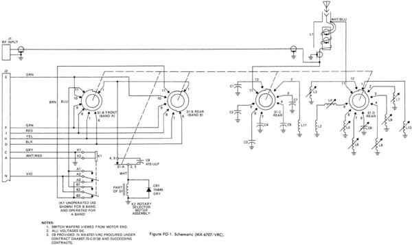
MX-6707 Schematic
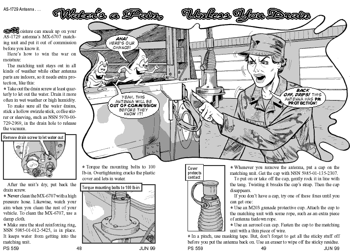
PM Magazine
Modifications
Take due caution when using this information
Adjusting low band to Ham 10 Meter (28-29mHz) or CB (27 Mhz)
- Take the bottom cover off the MX-6707 and look at the bottom of the unit with the coax cable/connector facing you.
- Find the 5th tuning capacitor (small screw driver adjustment) counting from the coax cable in a counter-clockwise direction. This capacitor C8 tunes the lowest band 30-33 MHz on the antenna and will allow you to match the antenna at a lower band
- Now with an SWR meter attached test to see where you are. Using the C8 adjustment (when making adjustments to C8 only use a plastic screw driver) tune it in.
- Reassemble and retest
Using with the Amateur 2Meter Band
Ive heard rumors that this antenna can be made to work on the Ham 2Meter band (144-148 mHz). I haven't tested this myself, but it could be possible, since a 2meter 5/8 wave is the same as a 6meter 1/4 wave. I've used the old radio shack 5/8 mag mount for 6 meters for a long time..
Testing to follow.
Reference Files
- OPERATOR’S, ORGANIZATIONAL, DIRECT SUPPORT, AND GENERAL SUPPORT MAINTENANCE MANUAL
- ANTENNA AS-1729/VRC (NSN 5985-00-985-9024)
- 23 January 1984
- ORGANIZATIONAL, DIRECT SUPPORT AND GENERAL SUPPORT MAINTENANCE REPAIR PARTS AND SPECIAL TOOL LIST
- (INCLUDING DEPOT MAINTENANCE REPAIR PARTS & SPECIAL TOOLS)
- ANTENNA AS-1729/VRC (NSN 5985-00-985-9024)
- 5 March 1985


