Difference between revisions of "AN~GRC-213"
RadioNerds (talk | contribs) (Created page with ";{{pdf|TM 11-5820-923-20P.PDF|TM 11-5820-923-20P}} ::ORGANIZATIONAL MAINTENANCE ::REPAIR PARTS AND SPECIAL TOOLS LIST ::RADIO SET AN/GRC-213 ::(NSN 5820-01-128-3935) ::ATTN: A...") |
|||
| (68 intermediate revisions by one other user not shown) | |||
| Line 1: | Line 1: | ||
| + | ==Overview== | ||
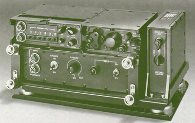
| + | [[File:GRC-213-0.png|400px|right]]The AN/GRC-213 is an HF low-power transceiver designed for use on wheeled or tracked vehicles. It has the capability of tuning 280,000 different frequencies within the 2– to 29.9999–MHz range. An internal antenna tuner automatically tunes the radio to match any of the three supplied antennas within the operating frequency range. The AN/GRC-213 is made up of Radio Set [[AN~PRC-104|AN/PRC-104(*)]], Amplifier-Power Supply AM-7152/GRC-213, interconnecting cables, and Speaker LS-454. The [[AN~PRC-104|AN/PRC-104(*)]] can also be used separate from the vehicle as a man pack radio set if desired | ||
| + | |||
| + | |||
| + | ===Brochure=== | ||
| + | <gallery widths=100px heights=100px perrow=5> | ||
| + | File:GRC-213-Brochure-Front.jpg | ||
| + | File:GRC-213-Brochure-Back.jpg | ||
| + | </gallery> | ||
| + | |||
| + | |||
| + | ==Capabilities and Features== | ||
| + | The AN/GRC-213 is an HF radio set that provides reliable long-range communication for wheeled or tracked military vehicles. The AN/GRC-213 incorporates the [[AN~PRC-104|AN/PRC-104(*)]] man pack radio (less battery pack) with an amplifier–power supply and loudspeaker to produce a vehicular system. The [[AN~PRC-104|AN/PRC-104(*)]] can also be used with a battery pack for man pack operation. For the detailed capabilities and features of the [[AN~PRC-104|AN/PRC-104(*)]], refer to the equipment description paragraph in [[media:TM_11-5820-919-12.pdf|TM 11-5820-919-12]]. The amplifier–power supply conditions and filters the vehicular power source for the radio set, in addition to amplifying and squelching the audio output to drive the external loudspeaker. The AN/GRC-213 is easy to install and remove because of quick-release fasteners and connectors. The AN/GRC-213 controls are easy to operate even if the operator wears gloves. Blackout operation is possible because audible indicators are used rather than lighted meters or indicators. These audible indicators provide warning of low vehicular power, transmitter failure, or antenna tuning fault. The watertight AN/GRC-213 maintains frequency stability over the operational temperature range of -46° to +71°C. Pushbutton frequency selection provides 280,000 channels from 2 to 29.9999 MHz in 100-Hz increments with selectable voice/data/cw modes in both upper or lower sideband operation. | ||
| + | |||
| + | ==AM-7152/GRC-213 Amplifier Power Supply== | ||
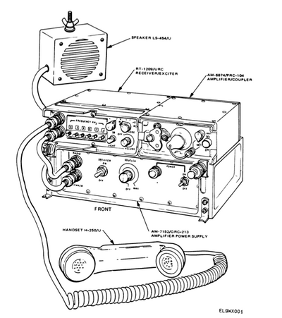
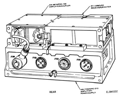
| + | The amplifier-power supply, together with interconnecting cables, provides interface and isolation between the [[AN~PRC-104|AN/PRC-104(*)]], Speaker [[LS-454~U|LS-454/U]], and the Vehicle Inter-communication System [[AN~VIC-1|AN/VIC-1(V)]]. The amplifier–power supply receives input power from the vehicle power source through an electrical power cable assembly. The amplifier-power supply fully conditions and filters the | ||
| + | power to protect the [[AN~PRC-104|AN/PRC-104(*)]] from over voltage, noise spike transients, radio-frequency interference (RFI), and reverse polarity. The conditioned and filtered power is sent to the amplifier/coupler through another electrical power cable assembly. An audio amplifier with squelch circuitry is provided in the amplifier-power supply for driving an [[LS-454~U|LS–454/U]] external loudspeaker with one watt of audio power. The amplifier-power supply can interface with the [[AN~VIC-1|AN/VIC-1(V)]] to provide a remote handset operation capability. It can also interface with the [[AN~VIC-1|AN/VIC-1(V)]] and a VHF FM radio set in the vehicle to provide retransmission capabilities. | ||
| + | |||
| + | [[File:AN_GRC-213.png|400px]] [[File:AN_GRC-213-1.png|400px]] | ||
| + | |||
| + | |||
| + | ===Specifications=== | ||
| + | ;Power protection | ||
| + | :Reverse connection and short circuit | ||
| + | ;Conditioned current | ||
| + | :5.5 amps maximum | ||
| + | ;Auxiliary current | ||
| + | :10 amps maximum | ||
| + | ;Conditioned voltage | ||
| + | :22 V dc minimum, with 26.5 V dc nominal input | ||
| + | ;Audio input power | ||
| + | :2 mW minimum from RT-1209/URC into 500 ohms | ||
| + | ;Audio output power | ||
| + | :1 W (300 to 3000 Hz) into 600 ohms, harmonic distortion 10% maximum | ||
| + | ;Unmuted audio output power | ||
| + | :100 mW into 600 ohms | ||
| + | ;Monitor amplifier audio output power | ||
| + | :0.16 V rms into 150 ohms | ||
| + | ;Audio frequency response | ||
| + | :300 to 3000 Hz 3 dB (1W) | ||
| + | ;Audio output muting (squelched) | ||
| + | :30 dB minimum | ||
| + | |||
| + | ====Squelch==== | ||
| + | ;Sensitivity | ||
| + | :Adjustable for 10 to 20 dB SINAD | ||
| + | ;Attack Time | ||
| + | :30ms maximum | ||
| + | ;Release time | ||
| + | :300 µs minimum | ||
| + | ;Hysteresis | ||
| + | :After un-squelching, the un-squelched condition is maintained for up to 2-dB reduction in signal. | ||
| + | |||
| + | |||
| + | |||
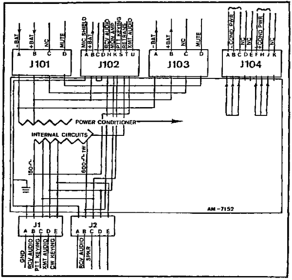
| + | ==AM-7152 Pinouts== | ||
| + | [[File:AM-1752_pinouts.png|600px|right]] | ||
| + | |||
| + | |||
| + | {| class="wikitable" style="border:2px solid black;width:25%;" | ||
| + | !colspan="2" style="font-size:125%;"|'''J-101''' | ||
| + | |- | ||
| + | | scope="row" style="border-top: 2px solid black;" |A | ||
| + | | style="border-top: 2px solid black;"|Bat - (Neg) | ||
| + | |- | ||
| + | | scope="row" style="border-top: 2px solid black;" |B | ||
| + | | style="border-top: 2px solid black;"|Bat + (Pos) | ||
| + | |- | ||
| + | | scope="row" style="border-top: 2px solid black;" |C | ||
| + | | style="border-top: 2px solid black;"|NC | ||
| + | |- | ||
| + | | scope="row" style="border-top: 2px solid black;" |D | ||
| + | | style="border-top: 2px solid black;"|Mute | ||
| + | |} | ||
| + | |||
| + | |||
| + | {| class="wikitable" style="border:2px solid black;width:25%;" | ||
| + | !colspan="2" style="font-size:125%;"|'''J-102''' | ||
| + | |- | ||
| + | | scope="row" style="border-top: 2px solid black;" |A | ||
| + | | style="border-top: 2px solid black;"|Mic Shield | ||
| + | |- | ||
| + | | scope="row" style="border-top: 2px solid black;" |B | ||
| + | | style="border-top: 2px solid black;"|Bat + (Pos) | ||
| + | |- | ||
| + | | scope="row" style="border-top: 2px solid black;" |C | ||
| + | | style="border-top: 2px solid black;"| | ||
| + | |- | ||
| + | | scope="row" style="border-top: 2px solid black;" |D | ||
| + | | style="border-top: 2px solid black;"| | ||
| + | |- | ||
| + | | scope="row" style="border-top: 2px solid black;" |H | ||
| + | | style="border-top: 2px solid black;"|Receive Audio | ||
| + | |- | ||
| + | | scope="row" style="border-top: 2px solid black;" |K | ||
| + | | style="border-top: 2px solid black;"|Mon Amp | ||
| + | |- | ||
| + | | scope="row" style="border-top: 2px solid black;" |S | ||
| + | | style="border-top: 2px solid black;"|PTT Keying | ||
| + | |- | ||
| + | | scope="row" style="border-top: 2px solid black;" |T | ||
| + | | style="border-top: 2px solid black;"|Retransmission | ||
| + | |- | ||
| + | | scope="row" style="border-top: 2px solid black;" |U | ||
| + | | style="border-top: 2px solid black;"|Transmit Audio | ||
| + | |} | ||
| + | |||
| + | |||
| + | {| class="wikitable" style="border:2px solid black;width:25%;" | ||
| + | !colspan="2" style="font-size:125%;"|'''J-103''' | ||
| + | |- | ||
| + | | scope="row" style="border-top: 2px solid black;" |A | ||
| + | | style="border-top: 2px solid black;"|Bat - (Neg) | ||
| + | |- | ||
| + | | scope="row" style="border-top: 2px solid black;" |B | ||
| + | | style="border-top: 2px solid black;"|Bat + (Pos) | ||
| + | |- | ||
| + | | scope="row" style="border-top: 2px solid black;" |C | ||
| + | | style="border-top: 2px solid black;"|NC | ||
| + | |- | ||
| + | | scope="row" style="border-top: 2px solid black;" |D | ||
| + | | style="border-top: 2px solid black;"|Mute | ||
| + | |} | ||
| + | |||
| + | |||
| + | {| class="wikitable" style="border:2px solid black;width:25%;" | ||
| + | !colspan="2" style="font-size:125%;"|'''J-104''' | ||
| + | |- | ||
| + | | scope="row" style="border-top: 2px solid black;" |A | ||
| + | | style="border-top: 2px solid black;"|Conditioned Power - (Neg) | ||
| + | |- | ||
| + | | scope="row" style="border-top: 2px solid black;" |B | ||
| + | | style="border-top: 2px solid black;"|Conditioned Power - (Neg) | ||
| + | |- | ||
| + | | scope="row" style="border-top: 2px solid black;" |C | ||
| + | | style="border-top: 2px solid black;"|Conditioned Power - (Neg) | ||
| + | |- | ||
| + | | scope="row" style="border-top: 2px solid black;" |D | ||
| + | | style="border-top: 2px solid black;"|NC | ||
| + | |- | ||
| + | | scope="row" style="border-top: 2px solid black;" |E | ||
| + | | style="border-top: 2px solid black;"|NC | ||
| + | |- | ||
| + | | scope="row" style="border-top: 2px solid black;" |F | ||
| + | | style="border-top: 2px solid black;"|Conditioned Power + (Pos) | ||
| + | |- | ||
| + | | scope="row" style="border-top: 2px solid black;" |H | ||
| + | | style="border-top: 2px solid black;"|Conditioned Power + (Pos) | ||
| + | |- | ||
| + | | scope="row" style="border-top: 2px solid black;" |J | ||
| + | | style="border-top: 2px solid black;"|Conditioned Power + (Pos) | ||
| + | |- | ||
| + | | scope="row" style="border-top: 2px solid black;" |K | ||
| + | | style="border-top: 2px solid black;"|NC | ||
| + | |} | ||
| + | |||
| + | ==PRC-104 Power Supply Cable== | ||
| + | The Power cable that provides filtered power to the PRC-104 is often difficult to source. I already had an "Extension" cable that is used to separate the Battery from the radio, so i decided to cut that cable and use Anderson Power Poles to create a multiple use cable assembly. If required, i can take this cable off and use it in the extender again, or hook this connector to another convenient power source. | ||
| + | |||
| + | |||
| + | {{message|image=Unverified.png|Special Note about Anderson Power Pole use in a 12 / 24 Volt Mixed environment|Anderson power poles are quite useful, however they can cause significant confusion and frustration when you are operating equipment in a mixed environment of 12 and 24 volts. Mixing the voltages can be disastrous to equipment, especially when accidentally putting 24 volts on a 12 volt radio. The normal side by side configuration of the 12 Volt connections is very standard, but there is no accepted universal method to handle 24 Volts. Some are trying a 90 degree rotation of one pole for 24 volt, but its far from universally accepted. At any rate I can always remove the pins from the connector and reinsert in whatever configuration i desire later without unsoldering..}} | ||
| + | |||
| + | |||
| + | |||
| + | [[File:GRC-213_PRC-104_power_cable.jpg|400px]] | ||
| + | |||
| + | Cable installed on the GRC-213 | ||
| + | |||
| + | |||
| + | |||
| + | [[File:GRC-213_PRC-104_power_cable-1.jpg|400px]] | ||
| + | |||
| + | Detail of the Power Cable | ||
| + | |||
| + | |||
| + | |||
| + | [[File:GRC-213_PRC-104_power_cable-2.jpg|400px]] | ||
| + | |||
| + | Detail of the 9 pin connector ABC is Negative, FHJ (this only has AB and FH soldered, i have since fixed it) | ||
| + | |||
| + | |||
| + | |||
| + | ====PRC-104 Power==== | ||
| + | One of the outer connections is negative (-) (use Meter to verify), center is positive (+) | ||
| + | |||
| + | [[File:PRC-104_pinout.png|400px]] | ||
| + | |||
| + | This is looking at the plug, NOT the radio. | ||
| + | |||
| + | ==Reference Files== | ||
| + | |||
| + | ===AN/GRC-213=== | ||
| + | ;{{pdf|TM 11-5820-923-10-HR.PDF|TM 11-5820-923-10-HR}} | ||
| + | :HAND RECEIPT | ||
| + | ::COVERING CONTENTS OF COMPONENTS OF END ITEM (COEI), | ||
| + | ::BASIC ISSUE ITEMS (Bll), AND ADDITIONAL AUTHORIZATION LIST (AAL) | ||
| + | ::RADIO SET AN/GRC-213 (NSN 5820-01-128-3935) | ||
| + | ::14 FEBRUARY 1986 | ||
| + | |||
| + | |||
| + | ;{{pdf|TM 11-5820-923-12.PDF|TM 11-5820-923-12}} | ||
| + | :OPERATOR'S AND ORGANIZATIONAL | ||
| + | ::MAINTENANCE MANUAL | ||
| + | ::RADIO SET AN/GRC-213 | ||
| + | ::(NSN 5820-01-128-3935) | ||
| + | ::14 FEBRUARY 1986 | ||
| + | |||
| + | |||
;{{pdf|TM 11-5820-923-20P.PDF|TM 11-5820-923-20P}} | ;{{pdf|TM 11-5820-923-20P.PDF|TM 11-5820-923-20P}} | ||
| − | :: | + | :ORGANIZATIONAL MAINTENANCE |
| + | ::REPAIR PARTS AND SPECIAL TOOLS LIST | ||
| + | ::RADIO SET AN/GRC-213 (NSN 5820-01-128-3935) | ||
| + | ::1 MARCH 1987 | ||
| + | |||
| + | |||
| + | ;{{pdf|TM 11-5820-923-34P.PDF|TM 11-5820-923-34P}} | ||
| + | :DIRECT SUPPORT AND GENERAL SUPPORT MAINTENANCE | ||
::REPAIR PARTS AND SPECIAL TOOLS LIST | ::REPAIR PARTS AND SPECIAL TOOLS LIST | ||
| − | ::RADIO SET AN/GRC-213 | + | ::(INCLUDING DEPOT MAINTENANCE REPAIR PARTS AND SPECIAL TOOLS) |
| − | + | ::RADIO SET AN/GRC-213 (NSN 5820-01-128-3935) | |
| − | |||
::1 MARCH 1987 | ::1 MARCH 1987 | ||
| − | |||
| + | ;{{pdf|TM 11-5820-923-40.PDF|TM 11-5820-923-40}} | ||
| + | :GENERAL SUPPORT | ||
| + | ::MAINTENANCE MANUAL | ||
| + | ::AMPLIFIER-POWER SUPPLY | ||
| + | ::AM-7152/GRC-213 (NSN 5820-01-127-5855) | ||
| + | ::14 FEBRUARY 1986 | ||
| + | |||
| + | |||
| + | |||
| + | ;{{pdf|TM_11-2300-476-14P.PDF|TM 11-2300-476-14P}} | ||
| + | :OPERATOR'S, ORGANIZATIONAL, DIRECT SUPPORT, AND GENERAL SUPPORT MAINTENANCE MANUAL | ||
| + | :(INCLUDING REPAIR PARTS AND SPECIAL TOOLS LIST) | ||
| + | ::INSTALLATION KITS, ELECTRONIC EQUIPMENT: | ||
| + | ::MK-2442/GRC-213 FOR ARMORED PERSONNEL CARRIER-M113A1 (NSN 5820-01-189-9791) | ||
| + | ::MK-2443/GRC-213 FOR UTILITY TRUCK-M151A1 (NSN 5820-01-189-9792) | ||
| + | ::MK-2444/GRC-213 FOR CARGO TRUCK-M561 (NSN 5820-01-189-9788) | ||
| + | ::MK-2445/GRC-213 FOR CARRIER COMMAND POST-M577A1 (NSN 5820-01-189-9793) | ||
| + | ::MK-2446/GRC-213 FOR TRUCK-M882 OR -M1008A1 [[CUCV]] (NSN 5820-01-189-9789) | ||
| + | ::MK-2447/GRC-213 FOR GENERAL PURPOSE WHEELED OR TRACKED VEHICLES (NSN 5820-01- 189-9790) | ||
| + | ::1 JANUARY 1987 | ||
| + | |||
| + | |||
| + | |||
| + | |||
| + | ===AN/GRC-213A=== | ||
| + | ;{{pdf|GTA_11-03-053.pdf|GTA 11-03-053}} | ||
| + | :Operating Procedures Short-Term Antijam (STAJ) Compatible Improved High Frequency Radio (IHFR) | ||
| + | ::Radio Sets | ||
| + | ::AN/PRC-104B | ||
| + | ::AN/GRC-213A | ||
| + | ::AN/GRC-193B | ||
| + | ::June 1992 | ||
| + | |||
| + | |||
| + | ;{{pdf|TM 11-5820-1047-20P.PDF|TM 11-5820-1047-20P}} | ||
| + | :ORGANIZATIONAL MAINTENANCE REPAIR AND SPECIAL TOOLS LIST | ||
| + | ::RADIO SET | ||
| + | ::AN/GRC-213A(V)1 (NSN 5820-01-262-9548) | ||
| + | ::15 MAY 1990 | ||
| + | |||
| + | |||
| + | |||
| + | ;{{pdf|TM 11-5820-923-40P.PDF|TM 11-5820-923-40P}} | ||
| + | :GENERAL SUPPORT MAINTENANCE | ||
| + | ::REPAIR PARTS AND SPECIAL TOOLS LIST | ||
| + | ::AMPLIFIER, POWER SUPPLY | ||
| + | ::AM-7152/GRC-213A(V)l | ||
| + | ::1 FEBRUARY 1990 | ||
| − | [[Category: | + | [[Category:Military/Radios]] |
| + | {{DISPLAYTITLE:AN/GRC-213}} | ||
Latest revision as of 17:57, 1 May 2016
Contents
Overview
The AN/GRC-213 is an HF low-power transceiver designed for use on wheeled or tracked vehicles. It has the capability of tuning 280,000 different frequencies within the 2– to 29.9999–MHz range. An internal antenna tuner automatically tunes the radio to match any of the three supplied antennas within the operating frequency range. The AN/GRC-213 is made up of Radio Set AN/PRC-104(*), Amplifier-Power Supply AM-7152/GRC-213, interconnecting cables, and Speaker LS-454. The AN/PRC-104(*) can also be used separate from the vehicle as a man pack radio set if desired
Brochure
Capabilities and Features
The AN/GRC-213 is an HF radio set that provides reliable long-range communication for wheeled or tracked military vehicles. The AN/GRC-213 incorporates the AN/PRC-104(*) man pack radio (less battery pack) with an amplifier–power supply and loudspeaker to produce a vehicular system. The AN/PRC-104(*) can also be used with a battery pack for man pack operation. For the detailed capabilities and features of the AN/PRC-104(*), refer to the equipment description paragraph in TM 11-5820-919-12. The amplifier–power supply conditions and filters the vehicular power source for the radio set, in addition to amplifying and squelching the audio output to drive the external loudspeaker. The AN/GRC-213 is easy to install and remove because of quick-release fasteners and connectors. The AN/GRC-213 controls are easy to operate even if the operator wears gloves. Blackout operation is possible because audible indicators are used rather than lighted meters or indicators. These audible indicators provide warning of low vehicular power, transmitter failure, or antenna tuning fault. The watertight AN/GRC-213 maintains frequency stability over the operational temperature range of -46° to +71°C. Pushbutton frequency selection provides 280,000 channels from 2 to 29.9999 MHz in 100-Hz increments with selectable voice/data/cw modes in both upper or lower sideband operation.
AM-7152/GRC-213 Amplifier Power Supply
The amplifier-power supply, together with interconnecting cables, provides interface and isolation between the AN/PRC-104(*), Speaker LS-454/U, and the Vehicle Inter-communication System AN/VIC-1(V). The amplifier–power supply receives input power from the vehicle power source through an electrical power cable assembly. The amplifier-power supply fully conditions and filters the power to protect the AN/PRC-104(*) from over voltage, noise spike transients, radio-frequency interference (RFI), and reverse polarity. The conditioned and filtered power is sent to the amplifier/coupler through another electrical power cable assembly. An audio amplifier with squelch circuitry is provided in the amplifier-power supply for driving an LS–454/U external loudspeaker with one watt of audio power. The amplifier-power supply can interface with the AN/VIC-1(V) to provide a remote handset operation capability. It can also interface with the AN/VIC-1(V) and a VHF FM radio set in the vehicle to provide retransmission capabilities.
Specifications
- Power protection
- Reverse connection and short circuit
- Conditioned current
- 5.5 amps maximum
- Auxiliary current
- 10 amps maximum
- Conditioned voltage
- 22 V dc minimum, with 26.5 V dc nominal input
- Audio input power
- 2 mW minimum from RT-1209/URC into 500 ohms
- Audio output power
- 1 W (300 to 3000 Hz) into 600 ohms, harmonic distortion 10% maximum
- Unmuted audio output power
- 100 mW into 600 ohms
- Monitor amplifier audio output power
- 0.16 V rms into 150 ohms
- Audio frequency response
- 300 to 3000 Hz 3 dB (1W)
- Audio output muting (squelched)
- 30 dB minimum
Squelch
- Sensitivity
- Adjustable for 10 to 20 dB SINAD
- Attack Time
- 30ms maximum
- Release time
- 300 µs minimum
- Hysteresis
- After un-squelching, the un-squelched condition is maintained for up to 2-dB reduction in signal.
AM-7152 Pinouts
| J-101 | |
|---|---|
| A | Bat - (Neg) |
| B | Bat + (Pos) |
| C | NC |
| D | Mute |
| J-102 | |
|---|---|
| A | Mic Shield |
| B | Bat + (Pos) |
| C | |
| D | |
| H | Receive Audio |
| K | Mon Amp |
| S | PTT Keying |
| T | Retransmission |
| U | Transmit Audio |
| J-103 | |
|---|---|
| A | Bat - (Neg) |
| B | Bat + (Pos) |
| C | NC |
| D | Mute |
| J-104 | |
|---|---|
| A | Conditioned Power - (Neg) |
| B | Conditioned Power - (Neg) |
| C | Conditioned Power - (Neg) |
| D | NC |
| E | NC |
| F | Conditioned Power + (Pos) |
| H | Conditioned Power + (Pos) |
| J | Conditioned Power + (Pos) |
| K | NC |
PRC-104 Power Supply Cable
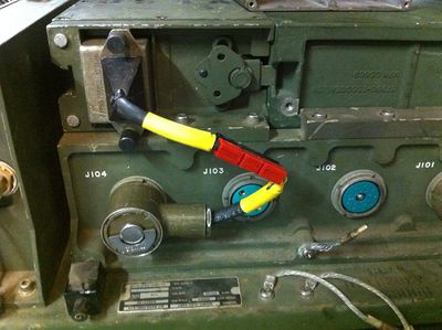
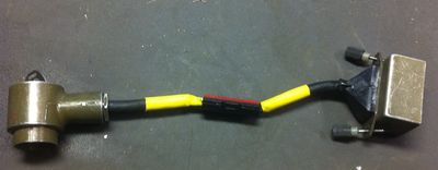
The Power cable that provides filtered power to the PRC-104 is often difficult to source. I already had an "Extension" cable that is used to separate the Battery from the radio, so i decided to cut that cable and use Anderson Power Poles to create a multiple use cable assembly. If required, i can take this cable off and use it in the extender again, or hook this connector to another convenient power source.
Cable installed on the GRC-213
Detail of the Power Cable
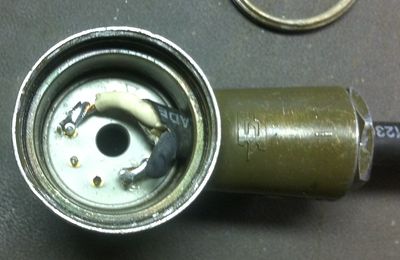
Detail of the 9 pin connector ABC is Negative, FHJ (this only has AB and FH soldered, i have since fixed it)
PRC-104 Power
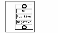
One of the outer connections is negative (-) (use Meter to verify), center is positive (+)
This is looking at the plug, NOT the radio.
Reference Files
AN/GRC-213
- HAND RECEIPT
- COVERING CONTENTS OF COMPONENTS OF END ITEM (COEI),
- BASIC ISSUE ITEMS (Bll), AND ADDITIONAL AUTHORIZATION LIST (AAL)
- RADIO SET AN/GRC-213 (NSN 5820-01-128-3935)
- 14 FEBRUARY 1986
- OPERATOR'S AND ORGANIZATIONAL
- MAINTENANCE MANUAL
- RADIO SET AN/GRC-213
- (NSN 5820-01-128-3935)
- 14 FEBRUARY 1986
- ORGANIZATIONAL MAINTENANCE
- REPAIR PARTS AND SPECIAL TOOLS LIST
- RADIO SET AN/GRC-213 (NSN 5820-01-128-3935)
- 1 MARCH 1987
- DIRECT SUPPORT AND GENERAL SUPPORT MAINTENANCE
- REPAIR PARTS AND SPECIAL TOOLS LIST
- (INCLUDING DEPOT MAINTENANCE REPAIR PARTS AND SPECIAL TOOLS)
- RADIO SET AN/GRC-213 (NSN 5820-01-128-3935)
- 1 MARCH 1987
- GENERAL SUPPORT
- MAINTENANCE MANUAL
- AMPLIFIER-POWER SUPPLY
- AM-7152/GRC-213 (NSN 5820-01-127-5855)
- 14 FEBRUARY 1986
- OPERATOR'S, ORGANIZATIONAL, DIRECT SUPPORT, AND GENERAL SUPPORT MAINTENANCE MANUAL
- (INCLUDING REPAIR PARTS AND SPECIAL TOOLS LIST)
- INSTALLATION KITS, ELECTRONIC EQUIPMENT:
- MK-2442/GRC-213 FOR ARMORED PERSONNEL CARRIER-M113A1 (NSN 5820-01-189-9791)
- MK-2443/GRC-213 FOR UTILITY TRUCK-M151A1 (NSN 5820-01-189-9792)
- MK-2444/GRC-213 FOR CARGO TRUCK-M561 (NSN 5820-01-189-9788)
- MK-2445/GRC-213 FOR CARRIER COMMAND POST-M577A1 (NSN 5820-01-189-9793)
- MK-2446/GRC-213 FOR TRUCK-M882 OR -M1008A1 CUCV (NSN 5820-01-189-9789)
- MK-2447/GRC-213 FOR GENERAL PURPOSE WHEELED OR TRACKED VEHICLES (NSN 5820-01- 189-9790)
- 1 JANUARY 1987
AN/GRC-213A
- Operating Procedures Short-Term Antijam (STAJ) Compatible Improved High Frequency Radio (IHFR)
- Radio Sets
- AN/PRC-104B
- AN/GRC-213A
- AN/GRC-193B
- June 1992
- ORGANIZATIONAL MAINTENANCE REPAIR AND SPECIAL TOOLS LIST
- RADIO SET
- AN/GRC-213A(V)1 (NSN 5820-01-262-9548)
- 15 MAY 1990
- GENERAL SUPPORT MAINTENANCE
- REPAIR PARTS AND SPECIAL TOOLS LIST
- AMPLIFIER, POWER SUPPLY
- AM-7152/GRC-213A(V)l
- 1 FEBRUARY 1990
